duncan
Active member
Hey gang,
First off, full disclosure: I'm posting this around a few forums to maximize how many eyes can see it and to cultivate the most amount of expertise as I can.
So after finishing my first amp build (an Express circuit), I've definitely caught the amp building bug.
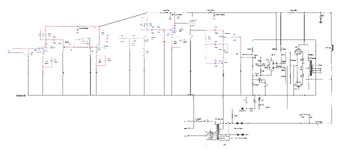
Instead of building an amp based off of a pre-made layout or design, I figured I would marry a preamp I love the sound of with a power section I love the sound of, while making a couple tweaks.
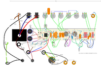
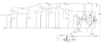
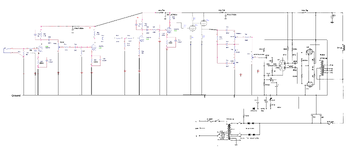
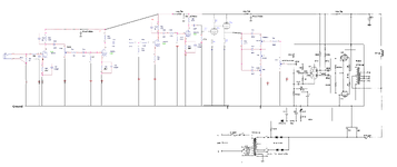
So I found schematics of the preamp, a cathode follower and EQ driver, and power amp, plunked them into photoshop, and put them all together in one package (hence the font differences).
Also, the schematic has component numbers assigned, but because of how the whole thing came together, I left them off the layout (but included the values). I left the heater wiring off for cleanliness.
The lead dress in the layout isn't what the end product would look like (I learned quite a bit about what to do and not to do on that front).
I took an initial run at converting the schematic to a DIYLC layout, but definitely made some errors. I posted over on EL34world and had a few guys offer some initial thoughts. I've also floated the schematic past a killer amp builder who makes a wide range of amps.
Would you guys be willing to have a look at the schematic and the layout, and let me know if you see any issues?
Thanks guys!
First off, full disclosure: I'm posting this around a few forums to maximize how many eyes can see it and to cultivate the most amount of expertise as I can.
So after finishing my first amp build (an Express circuit), I've definitely caught the amp building bug.
Instead of building an amp based off of a pre-made layout or design, I figured I would marry a preamp I love the sound of with a power section I love the sound of, while making a couple tweaks.
So I found schematics of the preamp, a cathode follower and EQ driver, and power amp, plunked them into photoshop, and put them all together in one package (hence the font differences).
Also, the schematic has component numbers assigned, but because of how the whole thing came together, I left them off the layout (but included the values). I left the heater wiring off for cleanliness.
The lead dress in the layout isn't what the end product would look like (I learned quite a bit about what to do and not to do on that front).
I took an initial run at converting the schematic to a DIYLC layout, but definitely made some errors. I posted over on EL34world and had a few guys offer some initial thoughts. I've also floated the schematic past a killer amp builder who makes a wide range of amps.
Would you guys be willing to have a look at the schematic and the layout, and let me know if you see any issues?
Thanks guys!