mosvalve power amp doesn't seem too loud = problem?

  • Thread starter Thread starter turmoil
  • Start date Start date
turmoil

turmoil

Active member
I recently purchased a used Mosvalve MV-942 (500 watt version) power amplifier. Upon taking off the top, because i heard something loose inside, what fell out was an OP-AMP that reads TLO72CP and TI22CB.

Now, the power amp does work just fine but i compared it to my Mosvalve MV-962 (100 watt version) and the MV-942 did not seem to be overwhelmingly louder than the MV-962; louder, yes but not like crazy louder. I did this test by plugging the same guitar and cable into one power amp (mono A channel) and one 4x12 cabinet with the Gain maxed and then the same setup with the other power amp.

My question is, could this OP-AMP just be a spare or something that was replaced? Could it have fallen out of the board, which i really doubt since there didn't appear to be any empty slots on the PCB. There are 4 other OP-AMPS (same exact ones as the "extra") that sit on the board currently but i'm curious because it doesn't seem too much louder than the other power amp. Should this be expected?

I also tested it in a W/D/W setup with my powerball and it kept up really well.
 
well, i sent an email to the TubeWorks tech but i'm not really counting on getting a response soon. i was hoping to find a schematic or something that might tell me if it's missing from the circuit. i kind of feel if it was though, it wouldn't work but that's just a guess.
 
i'll try to get a picture of it tomorrow if i can. the circuit seems to look much different from that of the 962
 
op amps in design can be parallel'ed in a pattern called ganging.

each time its gang'ed, the signal increases substancially, its basically how radios in vehicles work.

the other way to amplify a signal is using a transistor, in which if the bugger fell out, the amplifier wouldnt work at all.

im guessing it fell off the board from a cold solder. luckily it fell out of the chassis when it came loose and not laying on the PCB somewhere. could have probably shorted something out causing hellatious damage.
 
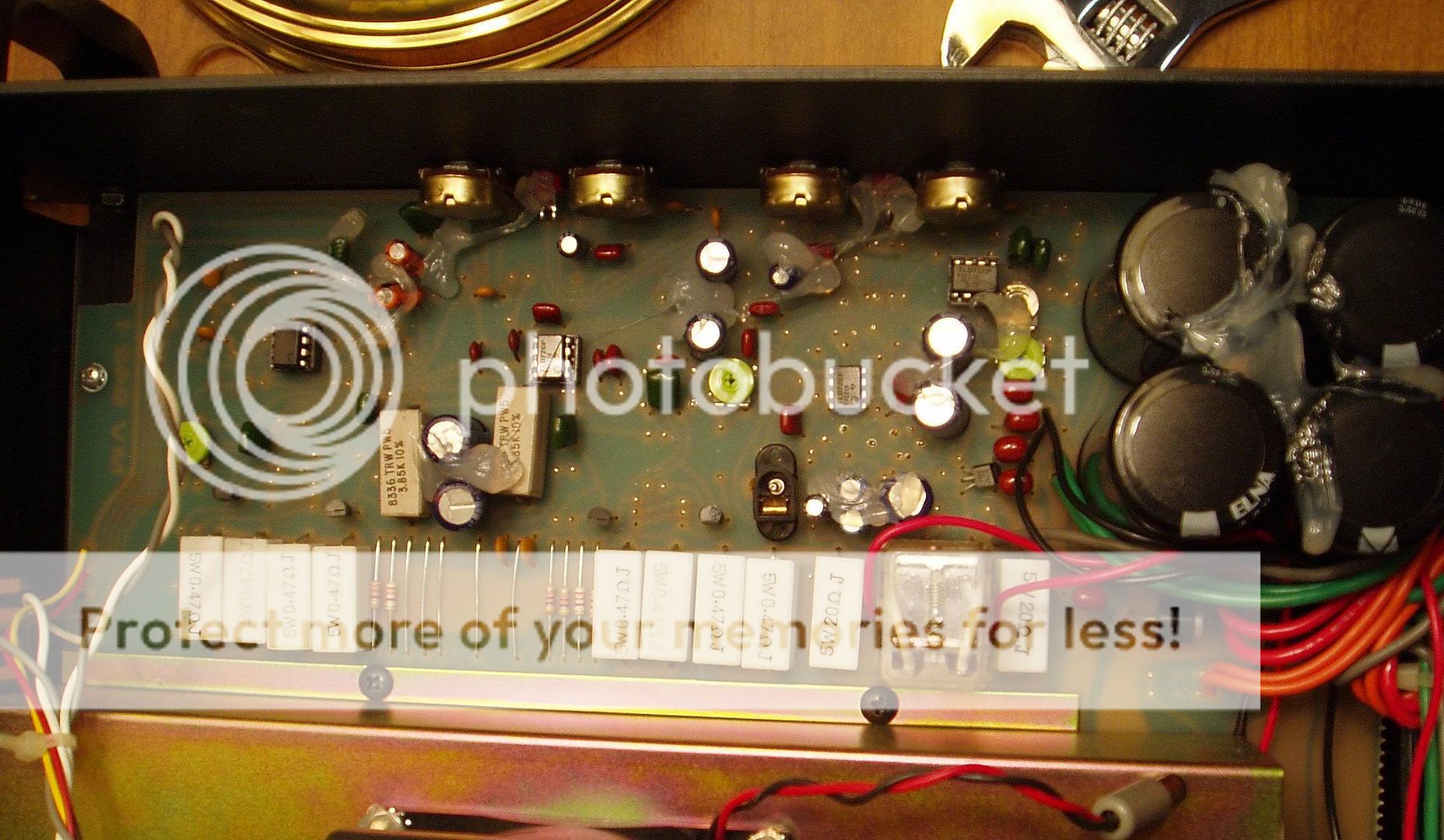
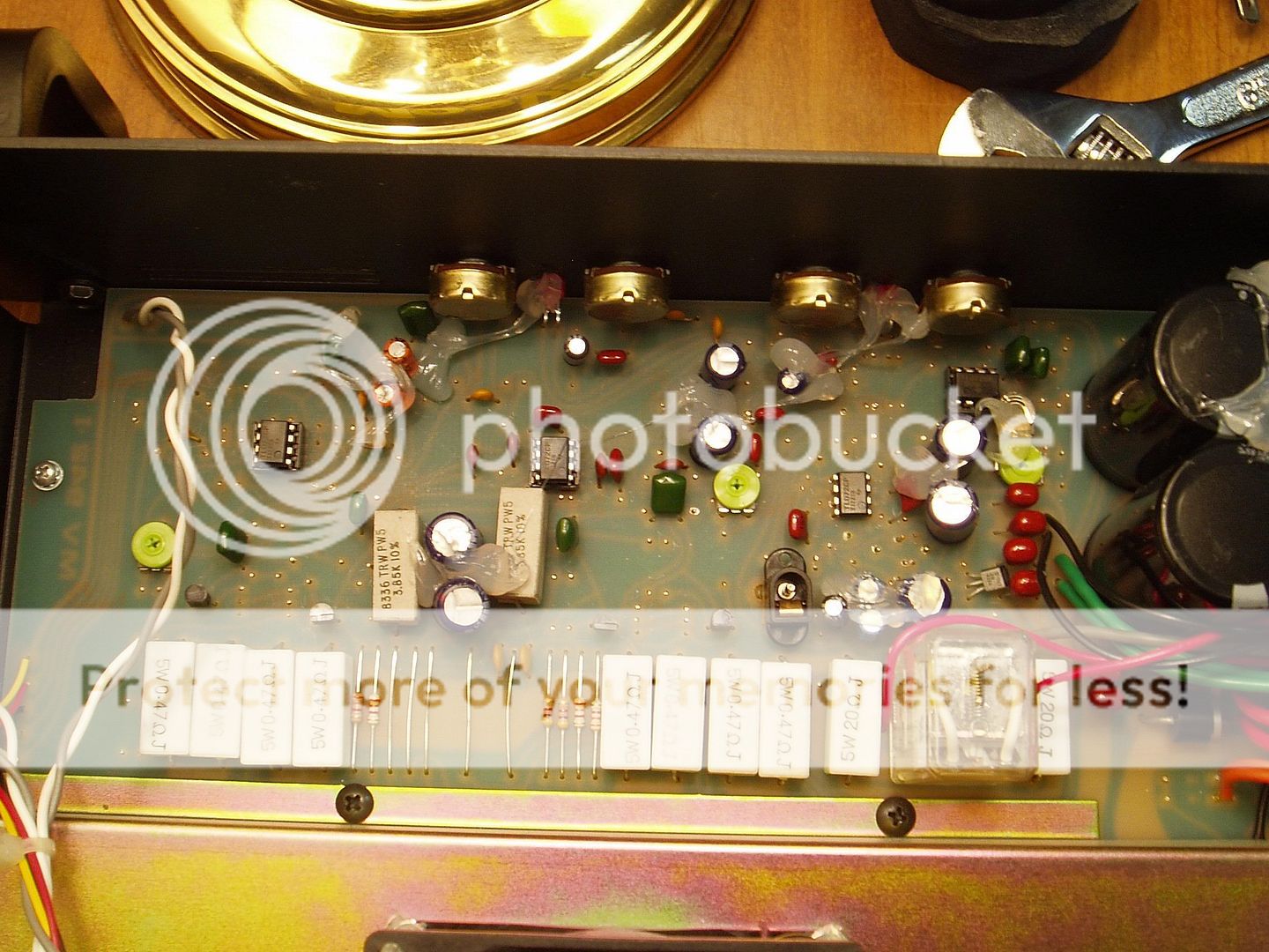
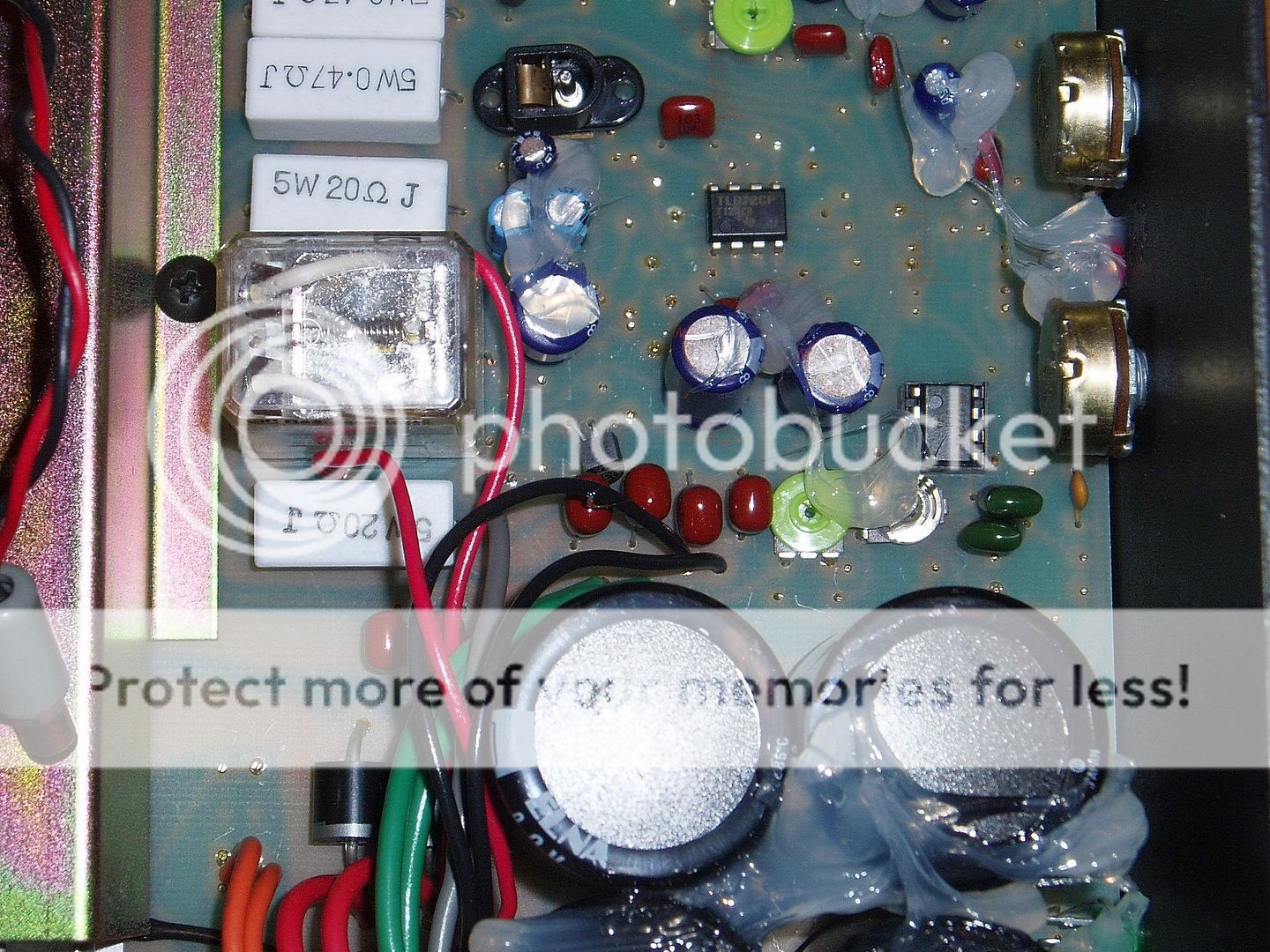
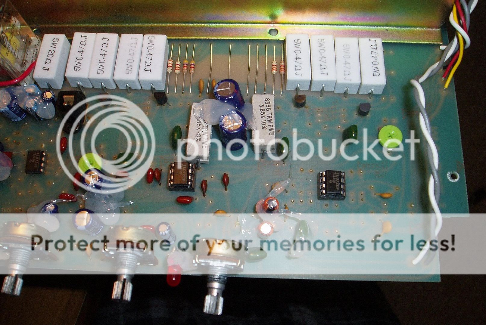
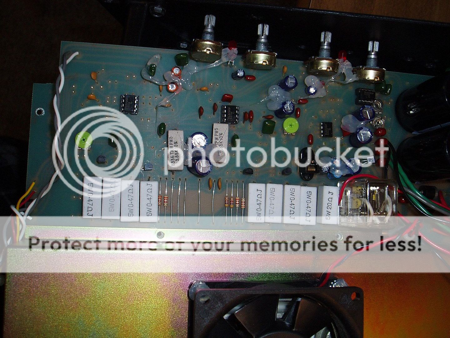
Here are some shots of the PCB.

mv1.jpg


mv2.jpg


mv3.jpg
 
did 2 of them fall out?

if so, i know the places where it looks like they go.

someone has worked on that amplifier it seems, because it is not common practice to ever solder op-amps directly on the PCB board, usually you always install an op-amp cradle first that the op-amps plug into for safe keeping. you see the other op-amps that have black things under them - thats the correct way to do it.

as far as which goes where, if there are 2 that fell out, i would need a schematic of it to tell you where it goes.

you also would want to order some 6/8-pin op-amp cradles so that they can be reinstalled correctly.

if you plan on doing this yourself, you would also need to get pin-out datasheets for each op-amp as to not plug them in the wrong way.

the op-amps might also be interchangable, sometimes IC's are like that - maybe the person replacing it used one of each but who knows. at this point it would be easier to take it to a tech so you know its done correctly, and possibly also fix the other IC that i see is directly mounted to the PCB board. those could come loose in the future if the solder jobs are also bad on them too.

solid state stuff isnt as forgiving as the tube stuff - the second you throw the switch and think its damaged, it already has if installed incorrectly.
 
What are you referring to? I see no other DIP8 pinouts on that board. can you explain where you see possibly two?
 
yeah sure no problem.

middle picture, theres what looks to be 4 .47 ohm 5W resistors in parallel with each other to what looks to be common ground, two sets of these 5W resistors.

on each side right above them looks like pin-out spacing for the op-amps.

im not familiar with that particular opamp at all, ive never used them myself so i dont know if its 2 in a single case or what, but its the only place i could tell that a component and trace combination looks fishy.

i dont have a schem, a layout, or anything. just what i see as the only possible area. unless that design uses a bi-component mounting system where theres more parts on the bottom.

from the pics, i dont notice anything else to be honest. that trace layout looks to be a few resistors in series with each other possibly too - it really depends on if there are more components on the bottom of the PCB.

you notice anywhere else? i cant see anything else that looks plausable :dunno:
 
another possible 8 pin location is in the middle pic, top right - between the first two potentiometers counting from the right. the spacing is a little wider than normal, but thats it.

like i mentioned before though at this point its best to send it to a tech. unless you are familiar with replacing op-amps and how to locate pin 1 and etc etc etc its best to leave it alone.

the fact that someone else might have worked on it makes it somewhat questionable. id send it in just to make sure it has a healthy checkup at the same time.
 
I do see the two spots you mention though those opamps have four legs each side in line, they wouldn't fit there.

the shiny spots in all of the "empty holes" on the PCB really look like resistor ends that are soldered on the opposite side of the board to me.


it is very strange that only one op amp is soldered directly to the board.

the tl072 is in fact a dual op amp.

I dunno what up from the pics, youll need a tech to look at it. you should also hunt down the schematic for it.

hey turmoil once you get the problem sorted out you should try swapping those op amps for some opa2134's I think you'll really like the improvement, and its simply plug n play. there are many other choices you can try too if your a tweaker but that's a great place to start. higher fidelity, quieter, just plain better.

http://shop.ebay.com/i.html?_nkw=OPA213 ... rom=&_ipg=
 
psychodave":3ffzaeok said:
moltenmetalburn":3ffzaeok said:
I do see the two spots you mention though those opamps have four legs each side in line, they wouldn't fit there.

the shiny spots in all of the "empty holes" on the PCB really look like jumper ends that are soldered on the opposite side of the board to me.


it is very strange that only one op amp is soldered directly to the board.

the tl072 is in fact a dual op amp.

I dunno what up from the pics, youll need a tech to look at it. you should also hunt down the schematic for it.

hey turmoil once you get the problem sorted out you should try swapping those op amps for some opa2134's I think you'll really like the improvement, and its simply plug n play. there are many other choices you can try too if your a tweaker but that's a great place to start. higher fidelity, quieter, just plain better.

http://shop.ebay.com/i.html?_nkw=OPA213 ... rom=&_ipg=

Interesting. I have the 962 and I was looking for something to increase the MosVlaves bass response. I will try the op-amp change you suggest.

I think you'll like the higher fidelity of the op amp though I cant say whether it will actually add bass or not, but for a tweaker its worth the few dollars to experiment. :thumbsup:
 
thank you very much for all the help guys! :thumbsup:

i have tried contacting TubeWorks' tech support but who knows if/when i'll get a response. I also found a guy on another board who supposedly has a schematic for it so hopefully he can send it my way. If that doesn't work then i have no clue.

Not that this probably makes a big difference but i did notice that both of the red LEDs do not light up at all. maybe they're burnt out?? :confused:

Also, does anyone know what those two lime green "pots" with the insert for a screwdriver control?
 
turmoil":n9apmbi5 said:
thank you very much for all the help guys! :thumbsup:

i have tried contacting TubeWorks' tech support but who knows if/when i'll get a response. I also found a guy on another board who supposedly has a schematic for it so hopefully he can send it my way. If that doesn't work then i have no clue.

Not that this probably makes a big difference but i did notice that both of the red LEDs do not light up at all. maybe they're burnt out?? :confused:

Also, does anyone know what those two lime green "pots" with the insert for a screwdriver control?

a schematic would tell everyone everything, including where those op-amps came from.

its kinda like asking wheres china, and not knowing which ways up, down, left, or right. its almost impossible to tell without documentation to help on a forum. someone with really good electrial experience could map a schematic from the PCB board traces and layout but that takes time in itself. doesnt do any good to do that either when the unit isnt working.

good luck on it keep us updated on how the op-amp changes sound :thumbsup: :rock:
 
Alright, so the guy from this other message board was kind enough to send me the copy of the schematic he received from Genz-Benz. It's a little hard to read but maybe some of you guys can make it out.

Here's a portion of the email he sent me that has some information that may be of importance:
The MV500 requires a "line level" signal input to get full output power. If you are inputting a low level signal, such as a guitar it will be low. In addition, according to a GenzBenz tech I talked to (GenzBenz owns MosValve) it needs an 8 ohm speaker load for maximum power output and no lower than 4 ohms.

MV500Schematic.jpg
 
how many op-amps fell out? you gave two numbers, but said "an op-amp"

i just want to make sure, i dont know them off the top of my head.

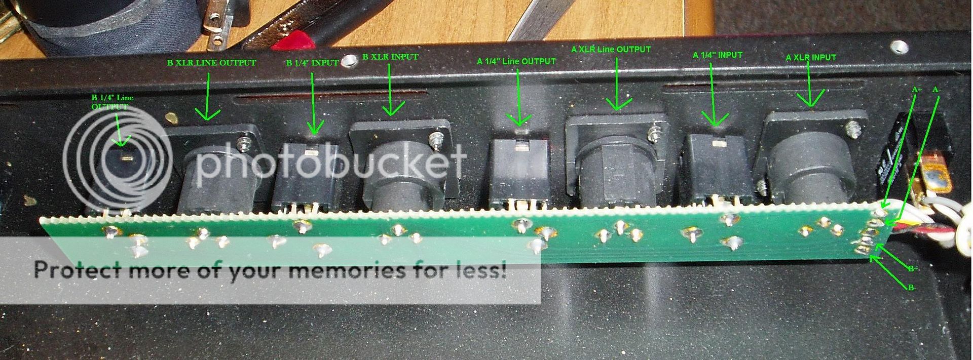
also, do you have a pic of where the inputs are for both channel A and channel B? it would help to be able to see the inputs in correlation to the rest of the pics so it would be easier to follow the signal path.

also, do you notice if there is one channel higher than the other?

there seems to be treble, gain, and presence controls from the schematic, but the treble control goes to a schematic symbol ive never run across before, looks like a JFET symbol sort of, but its not. its in series with a 680ohm and 2.2k resistor which branches off to those components.
 
glpg80":nude03tg said:
how many op-amps fell out? you gave two numbers, but said "an op-amp"

i just want to make sure, i dont know them off the top of my head.

also, do you have a pic of where the inputs are for both channel A and channel B? it would help to be able to see the inputs in correlation to the rest of the pics so it would be easier to follow the signal path.

also, do you notice if there is one channel higher than the other?

there seems to be treble, gain, and presence controls from the schematic, but the treble control goes to a schematic symbol ive never run across before, looks like a JFET symbol sort of, but its not. its in series with a 680ohm and 2.2k resistor which branches off to those components.

I didn't look at it closley but is it one of these mosfet symbols?,
 
glpg80":18reowh0 said:
how many op-amps fell out? you gave two numbers, but said "an op-amp"

i just want to make sure, i dont know them off the top of my head.

also, do you have a pic of where the inputs are for both channel A and channel B? it would help to be able to see the inputs in correlation to the rest of the pics so it would be easier to follow the signal path.

also, do you notice if there is one channel higher than the other?

there seems to be treble, gain, and presence controls from the schematic, but the treble control goes to a schematic symbol ive never run across before, looks like a JFET symbol sort of, but its not. its in series with a 680ohm and 2.2k resistor which branches off to those components.

1 op-amp fell out. There are two series of numbers on top of the op-amps which you can sort of see in a couple of the pictures.

Both of the channels seem to be about the same volume when maxed out or at the same settings.
 
Alright, i took out the entire PCB to get some better pictures of what's going on.

1) The inputs/outputs for the amp

ins_outs.jpg


2) Mosvalve PCB from underside - on far left you can see where the A+/A- and B+/B- come in from the ins/outs picture

mv_pcb.jpg


3) Close up of top of the PCB

pcb_guts.jpg


4) Another close up of the entire top of PCB

pcb_guts2.jpg


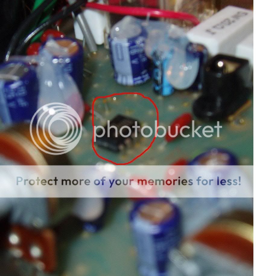
5) Behind the op-amp mounted directly to the PCB you can see there is a leg of wire sticking out. could this be from a component that fell out/broke off?

leg.jpg


Finally, i noticed that there appear to be 5 op-amps on the board in the schematic but on my board there are only 4 :doh:
I'm debating sending this thing back to the store i got it from for a refund rather than going through the headache of trying to trouble shoot an almost 20 year old amp. I would just hate to send it back to later realize it could have been fixed rather easily.
 
as far as the mosfet goes - you reminded me of what it is. its a P channel (normally on) MOSFET without the outer ring to denote a packaging, and there's 2 of them put together. 6 years of working on circuits and ive never seen a symbol like that. wierd. its on the top right hand corner of the A block channel after a (2k?) potentiometer. the same would exist for block B, however its a cutaway schematic.

as far as the board goes, yes you are right - there is nothing missing in yours. only 4 op-amps in the design and all 4 are accounted for both in trace design, placement, and function.

you might want to email genz benz about it, because you might have a treasure on your hands.... an early run mos-valve prototype that was made before the amplifier was functionally blueprinted and schematics were given out.

as for the op-amp, there is no telling where it came from or why. my guess is that someone could have glued it to the board upside down for an extra, and the glue simply came off.

but in the schematic, as far as i can tell from looking at the schematics those smaller pots are used for tuning the amplifier's frequency range, and the gains themselves are used for volume control. at least thats all i got to think about it.

call genz benz, give them the serial number and a few of these gut shots, and see what turns up. you never know.

i'd also recommend taking all of these pics back down from rig-talk after you are done.

who knows, ive heard people say the 2150 isnt any louder than other power-amps that exist. sometimes the headroom isnt what you'd expect.

thats not the most well designed amplifier ive seen in SS circuit design - in all of its simplicity. theres a few things they went around the long way with and theres not alot going on there which they deserve credit for, but the design took me a second to figure out. it made sense afterwards, but ive definately seen better.

i will give them credit where credit is due - what looks like hand soldering and a really nice and simple filtering design for a nice DC voltage that topples all marshall circuits and comes damn close to the Mesa strategy 400 poweramp. no wonder the mosvalve's sound good.
 
Back
Top