Need help with PT wiring for bias supply.

  • Thread starter Thread starter VaporDemon
  • Start date Start date
VaporDemon
VaporDemon
Member
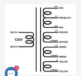
I’m sure this is pretty common knowledge but based on the diagram, how would I wire the 60V winding to use for my bias supply? I have a bias circuit already on the board which used a 60V tap on the original PT so I’m not sure what to do with the common. I’m assuming it’s supposed to be attached to ground but I’m not 100% sure so I’m asking to make sure. I know the heater winding is attached to ground with two 100 ohm resistors as a center tap but I couldn’t find any info that is helping me understand the 60V winding for my bias supply.

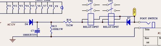
The second part of my issue is my original PT had a 12 volt winding which is attached to the channel switching circuit as shown in the other diagram. I’d like to change the relays to the 5 volt version & use the 5 volt winding to power it but my question is will I need to change the value of one of the resistors for it to work or should it theoretically operate the same as long as the supply voltage is correct for the relay? I understand the basic idea of how the switching circuit works but I’m unsure of how to calculate the resistor values. I do know with both relays operating I’m measuring 200mA of current on the supply leads. I am also planning on adding another relay which I was planning to operate from one of the relays that are already there.

Thanks in advance!!!
 

Attachments

  • IMG_2039.jpeg
    IMG_2039.jpeg
    70.8 KB · Views: 21
  • jet-city_jca50h_sch-2.jpeg
    jet-city_jca50h_sch-2.jpeg
    67.9 KB · Views: 22
Last edited:
The PT values are AC. You must rectify and filter and regulate down to get 5VDC. After you rectify and filter the 6V tap you’ll find you have more than 6V which is where the voltage regulator comes into play

Dual rectify the 60VAC tap by using a full wave rectifier to get 84VDC (peak voltage factor is 1.414)*Vsecondary and use 10uF caps to filter it. Remember bias supply voltages are negative not positive so pull from the correct side of the full wave rectifier.
Thanks for the info! Yes familiar with the PT secondaries being AC. On the switching schematic I attached the circuit already has half wave rectification and a filter in place and the PT winding is 5VAC are you suggesting I should implement a completely different rectification circuit and add a voltage regulator?

For the bias supply the existing bias circuit on my pcb has a half wave rectifier and filtering in place, is the method you are suggesting recommended instead for stability or performance or is it required because the new PT is a separate winding and not a tap like the original? I can post the bias schematic if needed but it’s basically the same as the SLO100 bias circuit.
 
Last edited:
Thanks for the info! Yes familiar with the PT secondaries being AC. On the switching schematic I attached the circuit already has half wave rectification and a filter in place and the PT winding is 5VAC are you suggesting I should implement a completely different rectification circuit and add a voltage regulator?

For the bias supply the existing bias circuit on my pcb has a half wave rectifier and filtering in place, is the method you are suggesting recommended instead for stability or performance or is it required because the new PT is a separate winding and not a tap like the original? I can post the bias schematic if needed but it’s basically the same as the SLO100 bias circuit.

Half wave rectifiers have a lower output voltage than full wave. There may not be enough negative voltage available after half wave rectification to bias four output tubes. Marshall only used a half wave rectifier for their bias supply on the 2203 but those had a 100V winding.
 
Half wave rectifiers have a lower output voltage than full wave. There may not be enough negative voltage available after half wave rectification to bias four output tubes. Marshall only used a half wave rectifier for their bias supply on the 2203 but those had a 100V winding.
Yes exactly - A 60VAC winding is much less than what’s typical on a 2203 bias PT secondary winding. You’ll need to go full wave and then adjust your voltage divider resistor to ground to set your desired bias range for the adjustable bias. Of course this is tube and amp specific.

Of course it should be noted the Vrms value of a pure sinusoid that is half wave rectified will be less than the VACpp, not more. 6Vpp half wave rectified is only 2.12Vrms ((6Vpp/2)*0.707). A half wave rectifier is off for a portion of the sinusoid so energy is tossed which is accounted for by using the Vpeak value and not Vpp. Full wave is on for twice the time of a half wave and two diodes are conducting at once hence the 1.414 and the use of the voltage as its stated across the secondary winding which is Vpp.
 
Last edited:
Half wave rectifiers have a lower output voltage than full wave. There may not be enough negative voltage available after half wave rectification to bias four output tubes. Marshall only used a half wave rectifier for their bias supply on the 2203 but those had a 100V winding.
This is a 50 watt Jet City which I Modded to be closer to SLO spec. The original PT had a 60 VAC tap on the high voltage windings which worked ok for two tubes. So since the original tap was 60 and worked just fine to bias two octal power tubes after half wave rectification, couldn’t the separate winding be used? I guess my question is if one were going to use such a winding, would the common be grounded and the other be attached to the half wave rect. and bias circuit the same way the tap was? I’m all for implementing the full wave setup but I’m just curious if it would work the other way assuming it was enough negative voltage after rectification. Thanks
 
Half wave rectifiers have a lower output voltage than full wave. There may not be enough negative voltage available after half wave rectification to bias four output tubes. Marshall only used a half wave rectifier for their bias supply on the 2203 but those had a 100V winding.
Just for reference here’s the mercury replacement which is almost identical to the original and I was wrong it’s a 63 volt tap.
 

Attachments

Yes exactly - A 60VAC winding is much less than what’s typical on a 2203 bias PT secondary winding. You’ll need to go full wave and then adjust your voltage divider resistor to ground to set your desired bias range for the adjustable bias. Of course this is tube and amp specific.

Of course it should be noted the Vrms value of a pure sinusoid that is half wave rectified will be less than the VACpp, not more. 6Vpp half wave rectified is only 2.12Vrms ((6Vpp/2)*0.707). A half wave rectifier is off for a portion of the sinusoid so energy is tossed which is accounted for by using the Vpeak value and not Vpp. Full wave is on for twice the time of a half wave and two diodes are conducting at once hence the 1.414 and the use of the voltage as its stated across the secondary winding which is Vpp.
This is a 50 watt Jet City amp which I modded to be closer to SLO spec. Attached is a factory replacement from mercury. The 63 VAC tap works just fine for two octal power tubes with half wave rectification. I guess I was just unsure what happens when it’s a separate winding instead of a tap. If it were hypothetically enough voltage then would the common be grounded, I wasn’t sure what happens with the common lead.
 

Attachments

 
Back
Top