1987x PPIMV help

  • Thread starter Thread starter Emg77
  • Start date Start date
Emg77

Emg77

Well-known member
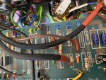
Looking for assistance on this PPIMV. Installed a metro loop and while I was in there was investigating the pre me installed PPIMV. It was under silicone looked a little suspect at any rate this brown wire came loose and I'm trying to figure out where it terminates. The 220k resistors are lifted. Anyways any assistance would be great.


https://imgur.com/gallery/LOb04b3
 

Attachments

  • BF5025C5-2BED-40BF-86E2-41C805BC87F3.jpeg
    BF5025C5-2BED-40BF-86E2-41C805BC87F3.jpeg
    320 KB · Views: 491
Well I assume that brown wire goes the outer lugs on one side of the dual gang pot? if so that is the bias voltage, and should be soldered to where it looks like it says r26, solder it to the resistor lead still connected to the board, not the lifted lead. You could solder it to the connected lead of either of those 220k's

Make sure you dont run your amp with that wire disconnected. your power tubes will red plate
 
Thanks! It certainly didn't look like it was great installed that way originally. I thought it might have been soldered to the lifted side of the resistor. So essentially connect it bypassing the resistor?
 
I think it would be good to measure for bias voltage at the power tube pins before flipping the standby switch. I would do it anytime I mess with a PPIMV.

I would also ziptie those shield wires together when you're done, each one providing a little support for the other (less likely to flop around and weaken/break wires near the solder joint).
 
Emg77":25ta0zv7 said:
Thanks! It certainly didn't look like it was great installed that way originally. I thought it might have been soldered to the lifted side of the resistor. So essentially connect it bypassing the resistor?


if its the standard LAR-MAR type PPIMV the the dual pot should be 250k, the resistors on the pot should be 2.2M, and the bias (your brown) wire should be soldered to the non-lifted side of the resistor.

Now that being said, did they do it right to begin with? who knows, that dry solder on that brown wire is rookie AF, it would have broken loose, and caused bad problems, you're lucky you knocked it loose.

If they did it wrong, and tied it to the lifted side your bias would be off when you tied it to the correct spot. The good news is, the bias would be off in the safe direction. i.e. you would have more bias voltage, making the tube run cold.

So I would put it where I suggested (that is if the pot is 250k, and the resistors on the pot are 2.2M) an you should check your bias.
 
Back
Top