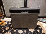
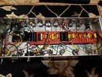
A little Christmas project I knocked together......

  • Thread starter Thread starter fusedbrain
  • Start date Start date
fusedbrain

fusedbrain

Well-known member
So I had some free time and ....well ..... :D
It's 2 x EL84's, cathode biased BE100 circuit built into an old 1x12 18watt tremolo combo I had kicking around, but never used.

No SAT, No Fat, and no HBE ( amp only has 3 x 12ax7's ) but it does have a depth control on the front panel, the 3 position gain structure switch and the C45 switch. I may still add a FAT switch in the plugged hole above the input jack.
Cab is loaded with a Heritage G12H30.

I just kinda made up the layout off the BE100 schematic that's floating around, and then fabricated the turret board to suit the BE100 preamp coupled to a cathode biased power section.
Plate voltage on the EL84's is 360V, with a tube rectifier and a 3H choke.
The filtering is 50uf mains, 16uf screens, 100uf PI, and 22uf x 22uf for the preamp, and I set up the power supply dropping string to give me 125volts on the first triode.
I also went with film vs electrolytic for the .680uf cathode bypass caps.
I would have used Synergy caps, but I didn't have enough of the right values on hand, so I went with the Mallory 150's, which I have a ton of.
The small value tone caps are 1000v CDE silver mica's, and all the snubber caps are 1kv BC ceramic.
Only other thing to note is the long-tailed pair PI is 470k / 470k / 820, with a 10k tail vs the standard 1M / 1M / 470 you usually see. The idea was to not drive the EL84's too hard, but I don't really know if these values will make that much difference.
A/B'd vs my Friedman BE100, it captures the vibe really well, and is going to be a nice little grab and go amp.
Pretty happy with how this turned out for something I only thought up 3 days ago while I was bored at work :lol: :LOL:
 

Attachments

  • BE 18watt 1.jpg
    BE 18watt 1.jpg
    335.7 KB · Views: 727
  • BE 18watt 2.jpg
    BE 18watt 2.jpg
    291 KB · Views: 738
  • BE 18watt 3.jpg
    BE 18watt 3.jpg
    252.8 KB · Views: 725
Sweet !!! Good luck with it !! How about some clips ?
 
You could always do the following to not drive those EL84’s so hard:

47k grid stoppers. (5.6k on Marshall). Mellows highs, rounds tone.

3k screen resistors. Adds back high end character.
 
Thanks for the suggestions guys!
I'm still playing with this a bit. There's not a ton of low end in this circuit. It's fine with a 4x12 cab, but it's not quite right with an open back 1x12 combo. I'm gonna play around with the first 2 coupling caps, and a couple other things, but I'll try those ideas out with the PI and screens.
 
swap out the 680n bypass cap on the first gain stage with a 2u2 Panasonic poly cap.
 
V2a":1odm273i said:
swap out the 680n bypass cap on the first gain stage with a 2u2 Panasonic poly cap.
Yes, I was going to look at the cathode bypass caps as well. My experience has been that when you compare film caps to electrolytic caps in cathode bypass positions, going from film to electrolytic of the same value is like moving up one value.
For example, to me, a .680uf electrolytic cap sounds similar to a 1uf film. The BE100 uses .680uf electrolytics for bypass caps, so I probably should have started with 1uf film, if I was going to use film caps there, or just used electrolytic.
Now, as luck would have it, I do happen to have a couple of Panasonic film caps in 1uf and 2.2uf, so they will definitely get tested out.
Thanks for the input :rock:
 
Think about the circuit and what you want to get out of your own amp, and don't be afraid to deviate from existing circuits.

The 2n2 coupling cap works with the output impedance of the first gain stage and the 68k/68k divider to roll off quite a bit of bass. So try stepping up the cathode bypass cap (well) beyond the BE value - most of that low end will be filtered out anyway. Then make the coupling cap switchable between something low (like 2n2) and something higher (6n8, 10n) for a lot more tonal variation.
 
Change your droppers to get that v1a plate voltage up to around 135v, and it should fatten up.

Also on PT20 Dave puts a .022uf on the second coupling capacitor instead of the .0022uf
 
Thanks for the ideas guys :rock:
V2a":2zlft1m0 said:
Think about the circuit and what you want to get out of your own amp, and don't be afraid to deviate from existing circuits.
Yup! If I'm going to make this work as a 1x12 18watt combo, I'm going to have to experiment.
Last night I changed out the 3 cathode bypass caps to .68uf electrolytic and installed the FAT switch to switch the first coupling cap to 22n from 2.2n. Also changed the speaker in the 1x12 cab to a M65 Creamback. ( I know the G12H30 has a slight bit more bottom end than the M65, but the overall tone of the Creamback is much nicer with this design).
The amp now sounds much closer to what I had in mind, but I still think there is room for improvement. I think the next move is going to be going up higher on the first cathode cap and adjusting the droppers to get a little more voltage on V1.
 
OK, I think I have this thing dialled in ....
First of all, I finally checked the bias on the EL84's and it was stupid hot! Like 125% hot :doh: :doh: :doh:
I have it running at 90% idle now. ( from what info I can find, this is a good value for cathode biased, push/pull class A/B EL84's)
Once I fixed that, I made a few more small changes, and things are sounding great now.
The grid stoppers on the EL84's were 1.5k. Raised them to 8.2k. Also increased the screen resistors to 2.2k. ( Thanks Psychodave )
I left the first 2 cathode caps at .68uf electrolytic, but raised the one before the CF to 330uf. ( Thanks V2A)
Went to a more conventional 1M / 470R / 1M PI, but with a 27k tail. ( Thanks V2a & CrazyNutz )
Lowered the first 2 droppers from 10k to 8.2k and I now have 138v on V1a. ( Thanks CrazyNutz )
I also changed the cap on the depth pot to .0068uf from .0047uf. The 4.7n was mucking with the lower mids. I just want the depth control to add a little 4x12-type thump to the 1x12 cab. Worked perfectly.

So all together, I now have a standard BE100 type preamp ( with the exception of the large bypass cap on V2a ), with FAT, Structure, and C-45, coupled to an cathode biased EL84 power section with a slightly modified PI and larger grid stopper and screen grid resistors values.
Standard presence, and depth control with a .0068uf depth cap. NFB is 47k off the 4ohm. All loaded into a nice portable little 1x12 combo cab with a G12M65 Creamback. :thumbsup:

Thanks again to all the guys who chipped in with suggestions. :rock:
 
I can’t take credit for what I mentioned. Mark Cameron helped me with my JCA 20 and suggested those mods.
 
Back
Top