davenotes
New member
I'm trying to execute what I understand is a relatively simple mod to allow me to footswitch between modes on Channel 1. I want to make sure I'm using the right input jack type and right wire gauge before I solder:
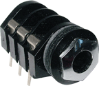
1. Stereo Input Jack: I am planning to drill a new stereo input jack into the back of the amp next to the Channel / Master input jack. The jack hardware that I plan to use is the S-H501-PC-S ... it's a stereo jack, metal nut, CLIFF, 6 PC MOUNT FOR MARSHALL pictured below. If anyone knows if this won't work please let me know. I decided not to use one of my existing speaker output jacks for fear of breaking something and also want to leave that jack available.
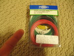
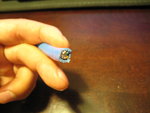
2. Wire Gauge: I'm planning to use 3 separate lead wires that are each color coded. 22 gauge, solid tinned copper, pictured below. They look fairly thin, but I think they would work. I saw one picture of someone's mod that used a very thick black wire that had 3 legs inside of it. I found one at a computer supply store that had 8 thin legs inside it, pictured below. Wondering what direction I should go.
Any help / thoughts?


