Marshall power supply question

  • Thread starter Thread starter SpiderWars
  • Start date Start date
SpiderWars

SpiderWars

Well-known member
I have a '74 Superlead that is not a super high voltage version, around 450-460vdc at 120vac. All of the power supply droppers are 8k2. There are two of them in series after the screens and then both of the preamp droppers are also 8k2. The amp also has a 22n coupler for the Bright channel instead of 2n2.

It seems a little fizzy. And since I was considering swapping out the 22n for a NOS Mustard 2n2 I thought that would be a good time to address the droppers. I have three old 10k Pihers so it won't look that off (the 8k2s are Iskra).

So which one or ones would you swap out if any? I don't have any voltages because I always run it variac'd so everything would be way off. The B+ I listed above is from when I bought it.

My first guess is to swap out both preamp 8k2s and leave both series 8k2s between screens and PI. Stock per schematic would be doing that plus swapping one of the other 8k2s.
 
What’s your intended goal here?

I prefer Iskra over Phier tonally. It’s splitting hairs though.
 
Well if you put the 10k droppers in then you're lowering the voltage even more in an already lower voltage amp. You might try the other direction with a 5k/8.2k after the screens rather than the 8.2k/8.2k

putting the 2n2 in place of the 22nf might help your fizz situation. Sometimes too much bass up front causes fizz.
 
What’s your intended goal here?
Reduce the fizz. Everything is higher voltage up front which is more gain throughout. And since the PI gets slammed so hard in these I wanted to keep the PI voltage up (increase headroom a tiny bit) while reducing the preamp voltages a little (reduce the signal a tiny bit). That's my thinking anyway.

But then the PI slams the grids of the power tubes so if the fizz is happening there this won't help that much I don't think. TBH, I don't need/want a bunch of extra gain, just normal amounts. I don't even want any cap on the V2 cathode, just the resistor is good.
 
Fizz... where is the NFB wire going? Is it the 4 ohm tap? Maybe try the 8 ohm tap. I wonder what the fizz cap is... 47pf? Maybe its drifted? Try a different value? Are the tubes good and power tubes matched? Presence pot and cap good? So many things cause fizz...

Also, you have a 50 year old amp. Make sure all of the jacks and pots have been cleaned. This can add unwanted sounds to an amp.
 
Has it always been fizzy as far as you know?
Is there a bright cap installed?
Have you tried swapping preamp tubes?
Dropping R's would not be a likely cause imo
 
Last edited:
Try a 12AT or AU tube for the PI ? Less gain to the power amp and lower impedance.
It's not like that...10x more subtle than either of those tube swaps. Those totally change the tone and amount of drive.

Fizz... where is the NFB wire going? Is it the 4 ohm tap? Maybe try the 8 ohm tap. I wonder what the fizz cap is... 47pf? Maybe its drifted? Try a different value? Are the tubes good and power tubes matched? Presence pot and cap good? So many things cause fizz...

Also, you have a 50 year old amp. Make sure all of the jacks and pots have been cleaned. This can add unwanted sounds to an amp.
4 ohm and 47pF. But none of this is really the question. The question is...since I'm already going to be in there with the board flipped, which resistors would you change? Its stock-but-not-stock as is. I could leave it, change one, two, or all three required to make it schematic-stock.

Has it always been fizzy as far as you know?
Is there a bright cap installed?
Have you tried swapping preamp tubes?
Dropping R's would be not be a likely cause imo
Yes its always had the fizz.
It did not have a bright cap but I immediately installed a 4700pF cap because that's the way I like a Superlead. It's not the bright cap, I have it my other Superleads too and they aren't fizzy.
Yes I've been thru tubes.
I don't expect the actual resistors to be the cause per se, just that the values are wrong. It increases the voltages such that everything has more gain than the next stage was designed to get.

But again, the question is really about which if any you would change "since you're already in there and you have the resistors". I mentioned the fizz because...well its fizzy. It still sounds pretty good for having a 22n coupler, which I think is at least partly to blame.
 
Last edited:
FWIW, I'm also changing the bias splitters that are not stock. They are carbon comp and they are tack soldered to the stubs of the original resistors. This thing takes 2 friggin days to reach an equilibrium idle. Not saying the bias splitters are the cause but carbon comp are very heat sensitive so I'm swapping them.
 
Fizz can be a pain to remove since varying locations are sources of it.

Look for high ESR in tonal capacitors in the signal path. I’ve found that to be a primary cause. You’ll see top end clarity traded for fizz if ESR is an issue.

The NFB path is an easy location to remove it - check the presence cap and the stock fizz cap - you may have to up it from 47 to 100 or check to see if it’s drifted.

You could put resistors in parallel to the 8.2k dropping resistors to decrease resistance which increases voltage to the plates, shifting the bias point to decrease distortion but increase voltage gain.

Fizz could also be a sign of instability.

Fizz could also be due to RF on the heaters coupling from some source or bad wiring practices.

Fizz could be do to bad grounding.

So in summary fizz can manifest as any single one of these problems or any combination of these.
 
But again, the question is really about which if any you would change "since you're already in there and you have the resistors". I mentioned the fizz because...well its fizzy. It still sounds pretty good for having a 22n coupler, which I think is at least partly to blame.
If I was already in there I would break the circuit like a passive FX loop and see if the FIZZ lives in the power amp or the preamp before changing out any components
Right where Q and Y are on this layout
https://ceriatone.com/british-style-plexi100-super-lead/just checked the link
if you scroll down to the layout for the 73 its the closest I can find to your circuit
 
Last edited:
I have a '74 Superlead that is not a super high voltage version, around 450-460vdc at 120vac. All of the power supply droppers are 8k2. There are two of them in series after the screens and then both of the preamp droppers are also 8k2. The amp also has a 22n coupler for the Bright channel instead of 2n2.

It seems a little fizzy. And since I was considering swapping out the 22n for a NOS Mustard 2n2 I thought that would be a good time to address the droppers. I have three old 10k Pihers so it won't look that off (the 8k2s are Iskra).

So which one or ones would you swap out if any? I don't have any voltages because I always run it variac'd so everything would be way off. The B+ I listed above is from when I bought it.

My first guess is to swap out both preamp 8k2s and leave both series 8k2s between screens and PI. Stock per schematic would be doing that plus swapping one of the other 8k2s.
What is your PI node supply voltage? Measure DC at the intersection of with 82k & 100k resistors at the PI. Ideally at normal mains voltage, or if variac'd let me know where you've set it.
 
If I was already in there I would break the circuit like a passive FX loop and see if the FIZZ lives in the power amp or the preamp before changing out any components
Right where Q and Y are on this layout
https://ceriatone.com/british-style-plexi100-super-lead/just checked the link
if you scroll down to the layout for the 73 its the closest I can find to your circuit
Thanks but I don't think that would work because almost all the distortion happen in the PI and power amp. So I'm 99.9% sure the fizz is happening after that point in the schematic.
What is your PI node supply voltage? Measure DC at the intersection of with 82k & 100k resistors at the PI. Ideally at normal mains voltage, or if variac'd let me know where you've set it.
Here's the B+ rail I wrote down when I got it. This was at just under 125vac wall voltage and the bias was set pretty cold (like ~50% max dissipation).
B+1 = 475
B+2 = 472
B+3 = 350
B+4 = 310
B+5 = 292

PI plates are 230/225.

B+4 and 5 seem high.
 
Last edited:
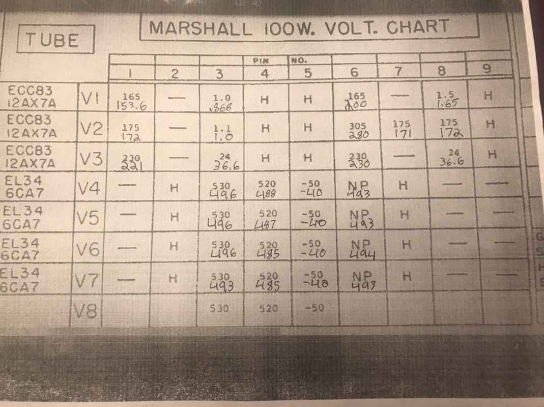
I just found this voltage chart. It shows a plate voltage of 496vdc and a V2-6 (aka B+4) voltage of 280vdc. Mine is 474vdc on the plates and 310vdc on V2-6. V1 Bright channel plate on mine is at 218vdc.

Marshall-Voltage-Chart.jpg
 
Last edited:
Thanks but I don't think that would work because almost all the distortion happen in the PI and power amp. So I'm 99.9% sure the fizz is happening after that point in the schematic.

Here's the B+ rail I wrote down when I got it. This was at just under 125vac wall voltage and the bias was set pretty cold (like ~50% max dissipation).
B+1 = 475
B+2 = 472
B+3 = 350
B+4 = 310
B+5 = 292

PI plates are 230/225.

B+4 and 5 seem high.
Yeah, too high for my liking. The sweet spot is B+3 at 330v in my view. I’d increase your droppers between the screen and PI nodes.
 
Yeah, too high for my liking. The sweet spot is B+3 at 330v in my view. I’d increase your droppers between the screen and PI nodes.
Would you leave the 8k2s in the peamp?

I was going to increase both of the preamp 8k2s but doing that without changing the screen/PI 8k2s would just increase the PI voltage so I'd have to swap one of the screen/PI 8k2s. And swapping all 3 makes it more like a typical Marshall supply with the 10k+8k2 in series then 10ks for the preamp.
 
It’s your instrument cable. The cathode of the ring is biased too high so you wanna get in there and get a 8n2cv dropper wired across the tip, careful not to redirect the electrons to the sniffer grid.
 
I changed one of the series resistors and the the one between the PI and V2. I left the last 8k2 coupler between V1 and V2. Also the 220k bias splitters and the 22n to 2n2 swap. Everything came out and went in pretty smooth.

Also, @Fusionbear told me on TGP that these turrets are occasionally found in Marshalls, apparently stock from factory. Who’d a thunk it.

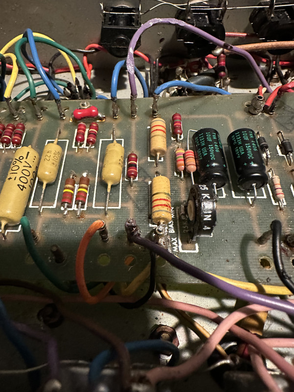
Before
That screen supply/choke connection point in foreground had two solder suckers full of solder (much of it obscured by the purple Presence control wire.
IMG-0689.jpg


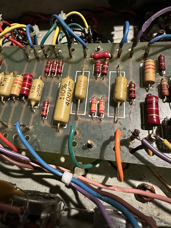
After
IMG-0820.jpg


And the 2n2 coupler, insulation burn was already there.
IMG-0821.jpg


I didn’t record the voltages before. It’s been setup for variac use and I’m not changing it back just to record the typical voltages. But anyway at 90vac here are the new voltages:

336
333
247
216
206

I’m taking a break then play it for a while.
 
That extra fizz on top is gone, probably due to the 2n2 coupler more than anything. And the bottom is perfect. This amp had JJ preamp tubes and JJ power tubes biased pretty cold and no Bright cap when I got it. So for my tastes it was really bassy and dark but with a sizzly top endy fizz too. Chinese preamp tubes and EH power tubes and a bright cap improved it a lot but these last changes really got it there. It's amazing what a few minor changes can make and also another example of how it's hard to do better than the stock circuit.

EDIT: Almost forgot the lowest hanging fruit:
IMG-0827.jpg
 
Last edited:
Back
Top