Renegade power question for Bruce

  • Thread starter Thread starter bamfx7
  • Start date Start date
bamfx7

bamfx7

New member
Under what test conditions does the Renegade output 65 watts?
 
With tube mix at 12:00 so all four tubes are active.
 
bruce egnater":191e7dxn said:
With tube mix at 12:00 so all four tubes are active.

Thanks. Can you provide more information?

What's the frequency response at a certain load impedance?

Input sensitivity?
 
bruce egnater":3884vw5v said:
What are you trying to figure out?

Right now, I'm just bench testing the amp and documenting operational specs.

Eventually I'll get around to looking at the reverb problem I mentioned before.
 
Bam, it's a guitar amp dude, it's not Crown Macro-Reference.

You're asking questions that 98% of the guitar amp builders on earth would NOT know. Why? Because no buyer gives a shit what the frequency response of amp is, or what it's input sensitivity is. Does it sound & feel good is all that matters.

The only time the specs you're asking matter is when you're attempting to 'borrow' someones design. If that's the case, have some respect for the designer, BUY the amp for yourself, and figure it out on your own. Coming onto a public forum and asking for possible company secrets is a pretty shallow thing to do.
 
I did buy this amp. I certainly would not say that a buyer wouldn't care about frequency response. Every poster on this board is constantly asking questions regarding "tone". They are always changing tubes, transformers and speakers looking for "tone".

I would have to disagree with a statement that assumes an inquiry is trying to "borrow" a design.
 
I get a funny feeling from this post also. I felt like he doesn't think it is actually a 65 watt amp. All he has to do is buy one, open it up, and I assume he can figure out what he wants. This post is odd.

:no: :confused: :gethim:
 
bamfx7":3lhldpls said:
I did buy this amp. I certainly would not say that a buyer wouldn't care about frequency response. Every poster on this board is constantly asking questions regarding "tone". They are always changing tubes, transformers and speakers looking for "tone".
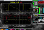
Frequency response means NOTHING in guitar amps because the guitar world has never even adopted a reference, quite simply because no one cares, and there is entirely too much 'mojo' to measure and/or qualify as usable data. Almost every guitar amp on earth has Treble, Mid, and Bass controls, but where are they flat, or better said, where do the knobs provide no cut or amplitude to the signal?? All the way off? Noon? Manufacturers don't even mark the front panel with how much amplitude you're adding when you turn the knob from zero to 10. Why? Because to be honest, most don't know because it's irrelevant in today's guitar world. If the guitar world could move out of the dark ages, the data would very useful, and a lot of the mojo would no longer even be in question.

You could input a standard test signal (pink noise) into your amp and measure it's output using SmaartLive or similar, but again, the data would mean nothing right now, unless you're just looking to kill time and compare two or more amplifiers to each other. I've done this before on a very well known amplifier, and you don't even want to know what I had to do with the T, M, and B controls to get the lower 'MAGNiTUDE' trace as flat as you would need to when trying to achieve the typical 'flat'. It was basically a completely unusable setting for playing guitar. Another thing is as soon as you change one setting, one tube, or even one cable, you'd have to reacquire the data and start over.

I applaud your enthusiasm to gather data, but I'm sorry to say, the guitar world is practically still in the dark ages when it comes to this type of thing.


Attachments

  • 4.99.jpg
    4.99.jpg
    194.1 KB · Views: 1,068
Klark, I appreciate your response. I have the capability to do all the tests you are referring to. My question was just to what spec Bruce designed his amp. I can test it all day long. That won't tell me what the original spec was and whether the amp is functioning at that spec at any particular time.

If Bruce decides to not disclose his spec, so be it. It doesn't hurt to ask.

He makes great products. I will continue to support him also.
 
Here is the basic test procedure for the Renegade. Infortunately the test "curves" are not in a format that I can copy here.
Don't know if this helps at all?


TEST PROCEDURE FOR RENEGADE
5/18/09
EGNATER/RENEGADE

TEST CONDITIONS:
117 VAC source
4 ohm load connected to MAIN (Use First) speaker output
Impedance slide switch set to 4 ohms
Both “TUBE MIX” set to center
MAIN 1, PRESENCE AND DENSITY set to center
All other knobs set to full CCW
Turn both rear panel bias current adjustments full CCW
Power switch to ON
Standby switch to STANDBY
DC VOLTAGE CHECKS
Bias supply voltage range check:
Voltmeter probe to junction of R8/R9.
Verify range of adjustment is -35VDC to -63VDC (minimum)
Set to and leave @ approx. -45VDC
Voltmeter probe to junction of R10/R11.
Verify range of adjustment is -35VDC to -63VDC (minimum)
Set to and leave @ approx. -45VDC
Turn STANDBY switch to ON
Voltmeter probe to QC22 on power supply PCB
Verify 455VDC (+/- 10 VDC)
Voltmeter probe to EL34 test point
Adjust EL34 bias adjustment to read 65mvDC (+/- 4mVDC)
Voltmeter probe to 6L6 test point
Adjust 6L6 bias trimmer to read 65mVDC (+/- 4mVDC)
Recheck EL34 bias test point to verify 65mVDC (+/-4mVDC) and readjust
if necessary.
LOW VOLTAGE CHECKS at CN5:
Measure +5VDC (+/- .4VDC) @ pin 1
Measure 0VDC (+/-.6VDC) @ pin 2
Measure +12VDC (+/-.6VDC) @ pin 3
Measure 0VDC (+/-.6VDC) @ pin 4
Measure -12VDC (+/- .6VDC) @ pin 5
Measure 0VDC (+/-.6VDC) @ pin 6
Voltmeter probe to QC21
Verify 12.3VDC (+/- .5VDC)


AUDIO TESTS:
1KHz/450mVAC signal into effects return jack
SW1 pushbutton in loop circuit is UP.
TUBE MIX knob on both channels at center
MAIN 1, Presence and Density at center
Channel 1 (green) on
Both reverb knobs CCW
Both 65/18 switches set to 65

POWER OUTPUT TEST:
4 ohm load connected to MAIN speaker output
Impedance slide switch set to 4 ohms.
Measure 16.2VAC (+/-.5VAC) at just before clipping.
Push front panel channel select button to verify output does not change

65/18 SWITCH TEST:
Reduce test signal to 300mVAC
Set both channels 65/18 switches to 18
Measure 9VAC (+/-.5VAC) at just before clipping
Push front panel channel select button to verify output does not change.
Channel 1 (green) ON
TUBE MIX knob to 6L6 measure 11VAC (+/- .5VAC) output
TUBE MIX knob to EL34 measure 13VAC (+/-.5VAC) output
Channel 2 (red) ON
TUBE MIX knob to 6L6 measure 11VAC (+/- .5VAC) output
TUBE MIX knob to EL34 measure 13VAC (+/-.5VAC) output

IMPEDANCE SWITCH TEST:
Set both 65/18 switches to 65
Increase test signal voltage back to 450mVAC
Change load to 8 ohms. Impedance selector switch to 8 ohms.
Measure 22.5VAC output
Change load to 16 ohms. Impedance selector switch to 16 ohms.
Measure 32VAC output

PEDAL, REVERB & LOOP TEST:
Input a 1KHz/10mVAC signal into the front panel input jack.
Check reverb level knob functions (see waveform)
Check pedal reverb functions

MAIN 2 TEST
Main 1, Presence, Density set to center
Both channel 65/18 switches to 65
Input a 1KHz/100mVAC signal into the effects return
MAIN 2 pedal button (light) off
Measure output 2.3VAC (+/- .2VAC)
MAIN 2 knob CCW
Turn MAIN 2 pedal on
Verify no change in output
MAIN 2 knob full CW
Measure 13VAC (+/- 1VAC) output

AP AUDIO TESTING
4 ohm load
Impedance switch set to 4 ohms
Both channel TUBE MIX knobs to center
PRESENCE AND DENSITY RESPONSE
100mVAC signal into effects return
TEST PLOT 1 Presence and Density full CCW
TEST PLOT 2 Presence and Density full CW
RECORD LINE OUT TEST
100mVAC signal into effects return
Presence and Density full CCW
SEE TEST PLOT
CHANNEL RESPONSE:
AP test signal level 15mvAC
Presence and Density full CCW

CHANNEL 1
PLOT GAIN BASS MIDDLE TREBLE VOLUME BRIGHT TIGHT 65/18
1 CTR CTR CTR CTR CTR UP/ON UP/ON 65
2 CTR CTR CTR CTR CTR DOWN DOWN 65
3 CTR CW CCW CW CTR DOWN DOWN 65
4 CTR CCW CW CCW CTR DOWN DOWN 65

CHANNEL 2
PLOT GAIN BASS MIDDLE TREBLE VOLUME BRIGHT TIGHT 65/18
1 9:00 CTR CTR CTR CTR UP/ON UP/ON 65
2 9:00 CTR CTR CTR CTR DOWN DOWN 65
3 9:00 CW CCW CW CTR DOWN DOWN 65
4 9:00 CCW CW CCW CTR DOWN DOWN 65


AP AUDIO TESTING:
4 ohm load
Impedance slide switch set to 4 ohms
10mVAC test signal
TUBE MIX to center
NOTE: All AP measurements performed with a short, shielded cable inserted into the effects loop from send to return.

CHANNEL 1
PLOT # VOLUME BASS TREBLE WATTS BRIGHT TIGHT
1 CTR CTR CTR CW UP/ON UP/ON
2 CTR CTR CTR CW DOWN/OFF DOWN/OFF
3 CTR CW CW CW DOWN/OFF DOWN/OFF
4 CTR CCW CCW CW DOWN/OFF DOWN/OFF


CHANNEL 2
PLOT VOL BASS MIDDLE TREBLE MASTER WATTS BRIGHT TIGHT
1 CTR CTR CTR CTR CTR CW UP/ON UP/ON
2 CTR CTR CTR CTR CTR CW DOWN/OFF DOWN/OFF
3 CTR CW CCW CW CTR CW DOWN/OFF DOWN/OFF
4 CTR CCW CW CCW CTR CW DOWN/OFF DOWN/OFF


RECORD/LINE OUT TEST
Remove test cable from effects loop
Test signal 1KHz/200mVAC into effects return jack
Set impedance slide switch to 8 ohms
XLR record out to AP in / see plot
 
bamfx7":1pyuevad said:
bruce egnater":1pyuevad said:
With tube mix at 12:00 so all four tubes are active.

Thanks. Can you provide more information?

What's the frequency response at a certain load impedance?

Input sensitivity?
AAAhhhh, just PLAY THE AMP!!!!!!!!!!
 
Back
Top