You are using an out of date browser. It may not display this or other websites correctly.
You should upgrade or use an alternative browser.
You should upgrade or use an alternative browser.
deleted
- Thread starter frettin
- Start date
glpg80
Well-known member
RedPlated
Well-known member
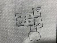
It's not a bright cap, it's a "dull" cap. A bright cap would connect across the first two lugs on the pot. This connects to ground on one side, so it is taking frequencies to ground through that 1000pf cap which will cut highs and some upper midrange. Only the frequencies allowed to pass through a 1000pf cap will be removed. Lows will not be affected.
When pushed in, the cap must go through the 150k resistor, plus the 68k in series, for a total of 218k between cap and ground. This will pretty much make it have little to no effect at that amount of resistance. Pulled, it does not parallel the resistors, that would require the 150k to be connected to BOTH sides of the 68k, which doesn't happen. What's happening here when you pull the pot, the middle and front lugs of the switch now connect and the signal now takes the least amount of resistance, only through the 68k, bypassing the 150k. Meaning more of the signal is passed to ground through the 1000pf cap, cutting more highs and upper midrange, thus the "Hi Cut" designation.
If you want a bright cap engaged by pulling the pot, that's very easy to do. But this isn't setup that way currently.
Last edited:
RedPlated
Well-known member
I typically use 1kv in that spot. 500v should be fine. I prefer ceramic caps.Thank you, you saved me hours of dicking around. Is it okay to use any type of capacitor? I see the existing ones used on the bright switch are 1KV and I just have little ones on hand probably not rated for that much voltage.
Last edited: