Elevated Heaters From A PT With No CT, WTF ?

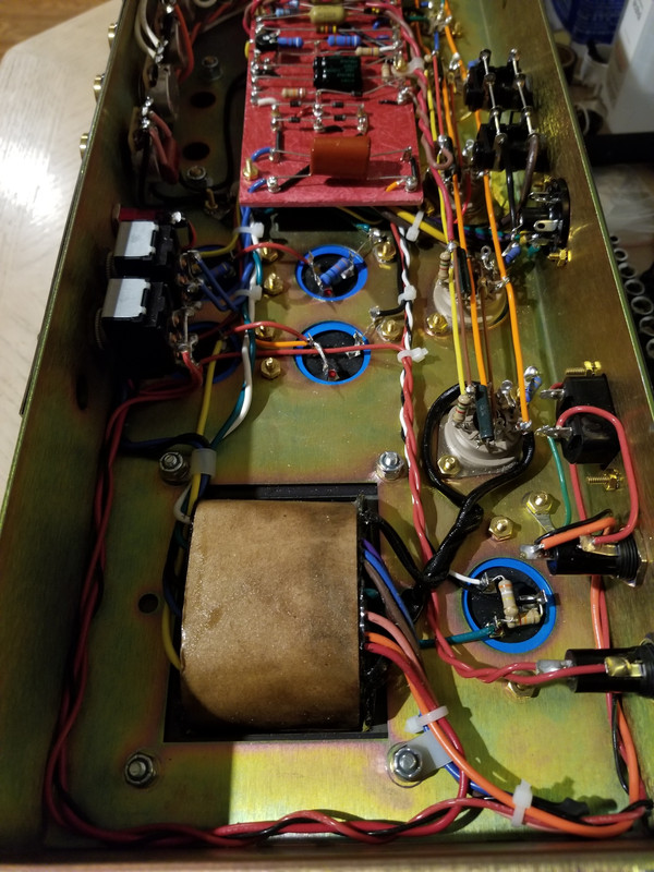
I'm building in an old combo amp chassis. The mains wiring, mains fuse, pilot light are all already in place.

The existing mains fuse is 1A 125V.. should I use a lower rating there ?

On the secondary I'd need to add another fuse holder. I'm thinking a 500mA fast-acting for that one ?

I don’t know your goal, you’ve never outlined what you’re doing or presented the full schematic? You can’t rate fuses based on hunches alone. Is this only a preamp design?
 
I don’t know your goal, you’ve never outlined what you’re doing or presented the full schematic? You can’t rate fuses based on hunches alone. Is this only a preamp design?
Yes, it's just a pre-amp. I'm powering two 12AX7's.

It's the "Snorkler" mod built as a stand-alone circuit in a chassis.

Under a load, I'm thinking I would fuse the PT secondary's at 500mA, fast-acting.
 
Yes, it's just a pre-amp. I'm powering two 12AX7's.

It's the "Snorkler" mod built as a stand-alone circuit in a chassis.

Under a load, I'm thinking I would fuse the PT secondary's at 500mA, fast-acting.

Merlin has a good writeup about power scaling for preamps. Poweramps get a bit more challenging.

I can’t for sure say they’re sized right for your goals. You’d need to run the math. Each preamp tube should draw the maximum amount you design it to since they always run class A. The heaters draw a lot of current, about 350mA or so per preamp tube. I’d say just on the heaters and mains alone your 1A slow blow mains would be close. The secondary would need to account for surge current with initial turn on.
 
Yes, it's just a pre-amp. I'm powering two 12AX7's.

It's the "Snorkler" mod built as a stand-alone circuit in a chassis.

Under a load, I'm thinking I would fuse the PT secondary's at 500mA, fast-acting.
I'd just put a 500mA fuse on the mains
I've yet to see any Rack preamps (Mesa,Langner,Brunetti,CAE,etc)with a fused secondary but it wouldn't hurt either I guess
 
Thanks guys !

I have an additional LittleFuse® 3AG fuse holder in the cart at Mouser, along with the flame-proof resistors for the heater elevation circuit.

I'll just order a variety of fuses at different ratings for the project.
 
Here's a pic of my Superlead build. Look at the blue 100u+100u cap can on bottom right. One of the 100u (the top one) is for the PI and then there is a 330k to the other 100u with a 82k resistor in parallel to the ground lug. I did not use flameproof as @glpg80 suggests, I learned something in this thread and hope to fix that someday.

EDIT: Looks like I changed the 330k to 390k or maybe that pic is when I first built it. I remember settling on 58vdc when I ran it at 120vac power.

There is a black wire connected to the ground lug that is hard to see, it routes that ground to a better ground point.

20210613_105706.jpg
Is that second fuse holder for a fusible link on the secondaries ?
 
I read somewhere that closer to 50-60DCV is better but 44DCV is still functional. I think I had like 46-48 when I did mine but my X-former had a center tap.

That RobRobinette site has alot of good stuff on it! Thanks Monomyth!:2thumbsup:
 
I read somewhere that closer to 50-60DCV is better but 44DCV is still functional. I think I had like 46-48 when I did mine but my X-former had a center tap.
If I use the formula B+ voltage x (100 / (220+100)) then based on that schematic I posted above I should get about 87V elevation.
 
If I use the formula B+ voltage x (100 / (220+100)) then based on that schematic I posted above I should get about 87V elevation.
I think there is an optimum DCV range that works best I thought it was 45-60 something like that I'll try to fine the information I have printed out on elevated heaters and see what it say exactly. I don't want to be quoting wrong numbers.:no:
 
I think there is an optimum DCV range that works best I thought it was 45-60 something like that I'll try to fine the information I have printed out on elevated heaters and see what it say exactly. I don't want to be quoting wrong numbers.:no:
Merlin's site says anything between 30~60 is good :

Heater Elevation
Elevation means referencing the heater supply to a DC voltage other than ground or zero volts. The heaters still operate at 6.3V or whatever, but this floats on top of the elevation voltage. Some valve stages such as cathode followers require the heater supply to be elevated to avoid exceeding the valve's Vhk(max) rating. But even when not explicitly needed, elevation can reduce hum in AC-heated circuits by reducing or saturating the leakage current between heater and cathode.*

The DC voltage is applied to a transformer centre tap, artificial centre tap, humdinger, or whatever reference connection the heater supply would normally have.

The elevation voltage can be taken from a potential divider across the HT (it doesn't matter where you position the divider), and an elevation voltage around 30 to 60V is typical. The divider should have a fairly high resistance so as not to waste current, although the lower arm (R2) should not be excessively large or Rhk(max) may be grossly exceeded, so it is advisable not to make it greater than 100k. The elevation voltage should be decoupled/smoothed with an arbitrarily large capacitor (C1), say 10uF or more.
 
You just have to change one of the values in the voltage divider to give more or less DCV.

My voltage divider was 470K/82K (to ground). Then you adjust or higher or lower on the 82K to get the DCV you want. Install a 100K to get more DCV or 56K to get less DCV. It will all depend on what your incoming tapped voltage is so you really just need to see what you get then go from there and adjust.

Yeah that valvewizard site was what I used as a reference as well in addition to seeing other peoples elevated heater designs and recommendations.
Yeah, but he advises not to go above 100K on the lower arm of the circuit.

So I'd need to increase the 220KΩ resistor.
 
Back
Top