ibzprestige
Active member
Bought the Mojotone British 50 Watt Master Volume kit, recieved it last Saturday and finished mid last week. I’ve done mods before but this was my first from scratch build, It was a lot of fun. I know some of the longer wires can be cleaned up, but there’s absolutely no noise when it’s on and turned up, so I’m in no rush with cleaning that up. Now looking for some little tweaks I can do to make it a little meaner, anyone have any suggestions? It is a 1978 JMP 2204 circuit.


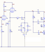
Wiring diagrams:
https://www.mojotone.com/Amp_Kits/British/British_50W_1978_2204_WD.pdf
Wiring diagrams:
https://www.mojotone.com/Amp_Kits/British/British_50W_1978_2204_WD.pdf