turmoil
Active member
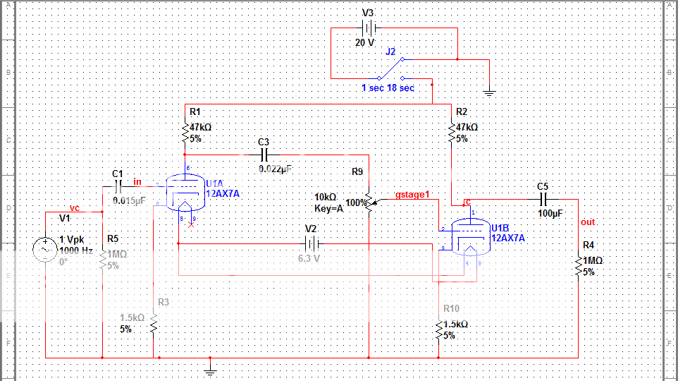
I'm working with a group here at my school and right now, we are working on prototyping this really stripped down tube circuit (see image below). The point of this circuit is 1) to show that we can actually build and analyze a tube circuit (since vacuum tubes aren't really taught in the classroom anymore) and 2) to verify our Multisim software model and see how it compares to the hardware model.
We built this circuit yesterday on a perf board and soldered all the connections exactly as they are on the schematic. We are using two DC power supplies to get us the heater voltages (6.3V) and the supply voltage (20V - yes, 20V not 200V). The reason for using 20V is because that is the largest DC supply we have in our lab currently.
The problem right now is that although the tube is heating/lighting up, it's not producing any output other than noise. Assuming all the solder connections and component connections are fine, what could be causing us to get no output other than noise?? I know you can operate 12AX7 tubes with this low of a supply voltage, according to datasheets, but in reality, is this just not possible?
Is there some connection that is not quite right with our model?
The tube socket we are using is similar to this image below. We left that tab in the middle unconnected. What is that tab used for since it is not labeled with a number like the other pins?

This software model puts out voltages that are clipped (depending on the potentiometer's value) and much larger than the input signal, but is this only valid because it's a theoretical model?
I know the preamp tube works -- it's a 12AX7 Mesa branded tube -- so the tube shouldn't be the issue. I do have others i could test with though.
I appreciate any insight you guys could provide")
I can also make the circuit available for download if that would make this easier to debug.
Thanks for reading!
We built this circuit yesterday on a perf board and soldered all the connections exactly as they are on the schematic. We are using two DC power supplies to get us the heater voltages (6.3V) and the supply voltage (20V - yes, 20V not 200V). The reason for using 20V is because that is the largest DC supply we have in our lab currently.
The problem right now is that although the tube is heating/lighting up, it's not producing any output other than noise. Assuming all the solder connections and component connections are fine, what could be causing us to get no output other than noise?? I know you can operate 12AX7 tubes with this low of a supply voltage, according to datasheets, but in reality, is this just not possible?
Is there some connection that is not quite right with our model?
The tube socket we are using is similar to this image below. We left that tab in the middle unconnected. What is that tab used for since it is not labeled with a number like the other pins?
This software model puts out voltages that are clipped (depending on the potentiometer's value) and much larger than the input signal, but is this only valid because it's a theoretical model?
I know the preamp tube works -- it's a 12AX7 Mesa branded tube -- so the tube shouldn't be the issue. I do have others i could test with though.
I appreciate any insight you guys could provide
I can also make the circuit available for download if that would make this easier to debug.
Thanks for reading!