Modding a 2204...

sahlomonic

Well-known member
Starting to apply the BE100 circuit to my Ceriatone 2204. Using my other Friedman modded amps as a tone reference, I'm getting close. The gain isn't quite hot enough, so I ended up removing the 470k to ground from the 3rd gain stage grid voltage divider (still attached in pic). Bottom end is lacking quite a bit, even with the fixed 220k/ 4n7 depth. I could put it on a pot, but would rather see what I can get back from the preamp. 2n2 couplers per the schematic, but thinking about changing one of them back to 22n, or even 4n7?

Also, tips and advice on how to better route and dress the wiring mods I did are appreciated. (SAT switch is next on the list to re-wire)
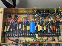

2204BE.jpg
 
Dang, I've got one of these too.. wish I had your knowledge to mod my Jet City 22H and Ceriatone 2204.
 
Dang, I've got one of these too.. wish I had your knowledge to mod my Jet City 22H and Ceriatone 2204.
It took me a while to understand the schematics, but honestly after I did it, it seemed easy. My next project is doing BE/HBE to my 50H (essentially the same layout as the 22H).

You could do the SLO mod to your 22H and it's super easy. It's just replacing a few resistors and capacitors, and 2 gain pots. Nothing is being re-wired like what I did to the 2204.

SLO mod and adding a Depth control was my first foray into modding a few years ago. Got my feet wet with that, then took the plunge on a JTM45 clone to give it a badass early EVH sound, and it turned out amazing. Then I converted a buddy's 68 Super Bass clone into about the same thing, and that thing packed a punch for sure. Just make sure your soldering skills are up to snuff, and understand how to safely work on an amp after discharging the filter caps so you don't get zapped even with it unplugged. Having said that, the 22H pretty much discharges completely right when you power it off, but there are plenty of YT vids to give you a visual aid on how to make sure it's safe.

Parts are cheap! You could probably get it done for about $30 and a few hours of your time once you get into it.

Edit: What I lack is the understanding of what each component relates to. Copying is one thing, but knowing what to change to get a desired result is what requires knowledge.
 
Last edited:
Starting to apply the BE100 circuit to my Ceriatone 2204. Using my other Friedman modded amps as a tone reference, I'm getting close. The gain isn't quite hot enough, so I ended up removing the 470k to ground from the 3rd gain stage grid voltage divider (still attached in pic). Bottom end is lacking quite a bit, even with the fixed 220k/ 4n7 depth. I could put it on a pot, but would rather see what I can get back from the preamp. 2n2 couplers per the schematic, but thinking about changing one of them back to 22n, or even 4n7?

Also, tips and advice on how to better route and dress the wiring mods I did are appreciated. (SAT switch is next on the list to re-wire)


View attachment 108434
For more gain, look at your plate load resistors. You could go up on the first stage a good amount and add a little gain. Personally, I don't like above 200k on the second stage. I can't see if it's stock, but changing your cathode bias resistors on the second stage will make a big difference. It's 10k stock and the BE uses something like 2.7k. For low-end, you could go higher on your cathode bypass caps, but I think things get a little too raw for me above .68uf, but if that's what you are after that will definitely add some low-end. I would also put the depth/resonance on a pot.
 
You need that grid reference to ground. Class A biasing adds a cathode resistor to make the cathode more positive than the grid, which is the same as making the grid more negative as the cathode. In the data sheets the maximum impedance for a grid leak resistor is 1Meg so at minimum you need to add a 1Meg resistor back in to ground at that voltage divider.
 
For more gain, look at your plate load resistors. You could go up on the first stage a good amount and add a little gain. Personally, I don't like above 200k on the second stage. I can't see if it's stock, but changing your cathode bias resistors on the second stage will make a big difference. It's 10k stock and the BE uses something like 2.7k. For low-end, you could go higher on your cathode bypass caps, but I think things get a little too raw for me above .68uf, but if that's what you are after that will definitely add some low-end. I would also put the depth/resonance on a pot.
Plates on V1 are 220k in series with 100k/470p. So you're saying back down from 330k total to no more than 200k? V1 cathodes are 2.7k/.68
 
Last edited:
You need that grid reference to ground. Class A biasing adds a cathode resistor to make the cathode more positive than the grid, which is the same as making the grid more negative as the cathode. In the data sheets the maximum impedance for a grid leak resistor is 1Meg so at minimum you need to add a 1Meg resistor back in to ground at that voltage divider.
I read on a few threads that removing the 470k to ground was a good move for more gain (maybe on a stock amp?), but you're saying I should have at least something going to ground? That voltage divider sets up the signal going to the PI, right? I can't remember if the stock voltage divider was 270/270 or 470/470 like I have it currently. Gain pot is also moved to that voltage divider, instead of coming off the v2b grid stock. (I think I'm relaying this correctly)
 
Last edited:
Look at it more as how the triode is biased correctly than as a voltage divider for the previous stage. You need the grid more negative than the cathode but in order for that to hold true they must both reference ground. The grid cannot be left floating.
 
Plates on V1 are 220k in series with 100k/470p. So you're saying back down from 330k total to no more than 200k? V1 cathodes are 2.7k/.68
I would, especially from 330k. That's too much for the second stage in my opinion. I think you would be better off with 330k on the first plate load and 220k on the second plate load. 2.7k/.68 is healthy on the first stage cathode, but I would try dropping the resistance on the second stage cathode if you haven't already. That will give you a good bit of difference. I can't tell if you did from the picture, kind of looks like you did. But, if 2.7k isn't enough, and you aren't that concerned about cleans, you can go even lower on both the first and second stage cathode bias. I prefer the 2.7-4.7k range on the second and using a clean boost if I needed more. The next step in gain would be to start adding clipping diodes. Also, I second glph80, you really need that resistor there.
 
Last edited:
yeah, put that 470k grid leak back in! Use an online voltage divider calculator to pick the values that you want, but also check a treble-peaking calculator to make sure the bypass cap does what you want. Rule of thumb, to increase gain but not change the frequency boost:

1. do not lower total resistance (470k+470k).
2. lower series resistance and increase shunt resistance accordingly.
3. if you cut series resistance in half, double the value of the bypass cap.
4. you might need to add a grid stopper resistor if you lower the series resistance significantly
 
Appreciate the info, fellas. Thank you!

As I eluded to earlier, I'm at a point where I can understand following a schematic and wire up accordingly, but the next phase I am wanting to learn is why values are what they are and how they relate to what you're trying to achieve.
 
I have a stupid question... the second cap and resistor pair starting from the left, I noticed you elongated the resistor wire to attach at both ends of the turrets but the first cap and resister pair is piggybacked.... is there a reason for that electronically or just how you wanted to do it on that pairing?
 
I have a stupid question... the second cap and resistor pair starting from the left, I noticed you elongated the resistor wire to attach at both ends of the turrets but the first cap and resister pair is piggybacked.... is there a reason for that electronically or just how you wanted to do it on that pairing?
No reason other than not realizing I could have piggybacked it and made it clean. Now that the circuit is sounding closer to how I want it, I can start dressing up my wiring.
 
Ok, changed a couple things based on what was discussed above. 100k V1B cathode, and reconnected the 470k ground off the voltage divider. That's all it needed!

Quick and dirty clip:


Sounds good!

You put a 100k on the cathode? That can’t be right, you meant anode right?
 
It took me a while to understand the schematics, but honestly after I did it, it seemed easy. My next project is doing BE/HBE to my 50H (essentially the same layout as the 22H).

You could do the SLO mod to your 22H and it's super easy. It's just replacing a few resistors and capacitors, and 2 gain pots. Nothing is being re-wired like what I did to the 2204.

SLO mod and adding a Depth control was my first foray into modding a few years ago. Got my feet wet with that, then took the plunge on a JTM45 clone to give it a badass early EVH sound, and it turned out amazing. Then I converted a buddy's 68 Super Bass clone into about the same thing, and that thing packed a punch for sure. Just make sure your soldering skills are up to snuff, and understand how to safely work on an amp after discharging the filter caps so you don't get zapped even with it unplugged. Having said that, the 22H pretty much discharges completely right when you power it off, but there are plenty of YT vids to give you a visual aid on how to make sure it's safe.

Parts are cheap! You could probably get it done for about $30 and a few hours of your time once you get into it.

Edit: What I lack is the understanding of what each component relates to. Copying is one thing, but knowing what to change to get a desired result is what requires knowledge.
My problem with the 22H is that it is a BFG modded one that I got from Guitar Center.. so it's already modded and I don't really understand what he has done compared to what it was before. I wish I would have got a couple of the 20Hs when they were blowing them out.

Does the Ceriatone 2204 discharge itself when you power it off? It's easier to trace a hand wired amp vs and PCB IMO.

If you pull the chassis and look at the board it might not be that difficult to figure out what the mods are.

I'm unsure if my 2204 has bleeder resistors on it, but I always bang out a big chord then pull the power (leave standby ON) to discharge it, then confirm with a multimeter.
 
Back
Top