anybody have or know of mods for marshall mark iii 2100?

  • Thread starter Thread starter donho
  • Start date Start date
D

donho

Member
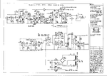
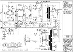
searching the web for a list of mods for the marshall mark iii 2100 head.
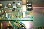
did some updating on my 2100, filter cans, bias resistors,new output trans,tubes and a few electralytic caps.
just wanted to clean things up and update due to the age of the amp.
anyways would like to check into the nfb and other mods.
but dont see much for the 100 watter.
some say remove the zener diodes, but what does that do?
some say clip D1?
some say make r1 68k, but these amps have 2 pcb and they also repeat resistor numbers on both pcb. so a person needs to know is it r1 on the front pcb or r1 on the rear pcb?

gonna try a nfb mod i found. it states add a 1.8 or 2.2k resistor // with R6. now like i said there are two r6 locations. one is on the front pcb and the other is on the rear. the tech explained it is the one on the rear pcb.
gotta wait for parts now.
thanks for any help/ :rock:
 
hope this helps.
 

Attachments

  • marshall_jcm900_25xx_45xx_50w.pdf_1.png
    marshall_jcm900_25xx_45xx_50w.pdf_1.png
    89.7 KB · Views: 3,735
  • 129219_marshall-jcm900-jcm900-pdf.jpg
    129219_marshall-jcm900-jcm900-pdf.jpg
    236.5 KB · Views: 3,746
here is a pic of what i mean by 2 resistor locations.
this guy says to add a 1.8k or 2.2k resistor // to r6.
this is the nfb mod
 

Attachments

  • jcm-900-mkiii-r6-no-yes.jpg
    jcm-900-mkiii-r6-no-yes.jpg
    439.4 KB · Views: 3,920
Much better schematic this time, good find.

The zener diodes D1 and D2 are responsible for clipping the positive and negative portions of the input signal once it reaches a certain point in either direction. Due to their placement in the input of the circuit, these will not add "gain" but will increase compression due to the input being clipped. Removing both diodes is unnecessary, as clipping D1 will have the same effect as it breaks the circuit. If I were you, I would just unsolder the + leg of D1 and raise it above the board, that way if you don't like the change, you can put it back to stock later.

The 10k resistor is probably fine the way it is, however, after the diodes are out of the circuit you may want to raise the value to 33k or 68k as this will help against overloading the input stage leading to slightly fuzzy sounding gain. Another plus of a higher value here (if its something you want) is that due to the Miller effect, some of the harsher highs will be rolled off before being amplified into the rest of the circuit.

For the placement, just follow the wires from the input jack to the board and follow the trace until you find a 10k resistor (Brown, Black, Orange). This is your input resistor, the rest of the input circuit should be in the vicinity.

All of this stuff though, I would tack up to "if it needs it" or if you don't really like the amp as is. These components are somewhat unique to the JCM900, and help give it its signature sound. If you start removing stuff, it's going to lose that.
 
donho":o4fnq1fq said:
some say remove the zener diodes, but what does that do?
some say clip D1?
some say make r1 68k, but these amps have 2 pcb and they also repeat resistor numbers on both pcb. so a person needs to know is it r1 on the front pcb or r1 on the rear pcb?

gonna try a nfb mod i found. it states add a 1.8 or 2.2k resistor // with R6.
It's difficult to read some of the values in the schematics posted so take with salt.
The 68k r1 mod and removing zeners makes the input look more like a regular (older) input. Since that should be the input then whichever pcb is connected to input jack should be the one. I'm not even sure you'll notice a difference. The zeners (I think it says 9.1v) shouldn't be doing anything to a guitar signal at the input jack.

If it were me I'd prob focus on changing V1 to a good cascaded/modded Marshall preamp. Similar to the Jose/Friedman/Cameron-type schematics but no Jose MV/diodes (yet), just the hot-rodded preamp part. I wouldn't even mess with anything else at first, just V1 up to the input of V2. The rest of the amp looks close enough (in practice) if not already correct to most other Marshalls. Hope that helps and good luck!
 
thanks guys.
amp does sound great. just thought there maybe something else i would like to try.
any thoughts on the neg fback mod? guy states its the reason why the jcm 900 amp is the quietest of the 100 watt line.
 
JakeAC5253":1u46fchq said:
Much better schematic this time, good find.

The zener diodes D1 and D2 are responsible for clipping the positive and negative portions of the input signal once it reaches a certain point in either direction. Due to their placement in the input of the circuit, these will not add "gain" but will increase compression due to the input being clipped. Removing both diodes is unnecessary, as clipping D1 will have the same effect as it breaks the circuit. If I were you, I would just unsolder the + leg of D1 and raise it above the board, that way if you don't like the change, you can put it back to stock later.

The 10k resistor is probably fine the way it is, however, after the diodes are out of the circuit you may want to raise the value to 33k or 68k as this will help against overloading the input stage leading to slightly fuzzy sounding gain. Another plus of a higher value here (if its something you want) is that due to the Miller effect, some of the harsher highs will be rolled off before being amplified into the rest of the circuit.

For the placement, just follow the wires from the input jack to the board and follow the trace until you find a 10k resistor (Brown, Black, Orange). This is your input resistor, the rest of the input circuit should be in the vicinity.

All of this stuff though, I would tack up to "if it needs it" or if you don't really like the amp as is. These components are somewhat unique to the JCM900, and help give it its signature sound. If you start removing stuff, it's going to lose that.

thanks. by D1 do you mean ZD1 or D1. because there is both. also which is the + side?
 

Attachments

  • 003.JPG
    003.JPG
    1.6 MB · Views: 3,335
donho":1jrc1je2 said:
skoora":1jrc1je2 said:
The best mod for a 900 is posting it for sale. :lol: :LOL:
you must be talking DR. or jvm :lol: :LOL:

Afraid not. I find all 900's fall way short. I was 20/21 when they first came out and they were not well received by me or anyone I knew. Especially thos shitty 9000 series preamps. It was another reason the dual rec really took off. Marshall did not have something great in the market at the time. I still remember playing the first Dual Rec's and not gelling with that big, but at the same time, soft sound they had. I was way too Marshall orientated at the time to like it. So I stuck with 800's and got one of the early Plexi reissues that started in '93, I think. Now that was some glorious Marshall. Plus you could get mid/late 60's Bassman heads back then for $175-250 a pop.
 
donho":z4msn5uz said:
JakeAC5253":z4msn5uz said:
Much better schematic this time, good find.

The zener diodes D1 and D2 are responsible for clipping the positive and negative portions of the input signal once it reaches a certain point in either direction. Due to their placement in the input of the circuit, these will not add "gain" but will increase compression due to the input being clipped. Removing both diodes is unnecessary, as clipping D1 will have the same effect as it breaks the circuit. If I were you, I would just unsolder the + leg of D1 and raise it above the board, that way if you don't like the change, you can put it back to stock later.

The 10k resistor is probably fine the way it is, however, after the diodes are out of the circuit you may want to raise the value to 33k or 68k as this will help against overloading the input stage leading to slightly fuzzy sounding gain. Another plus of a higher value here (if its something you want) is that due to the Miller effect, some of the harsher highs will be rolled off before being amplified into the rest of the circuit.

For the placement, just follow the wires from the input jack to the board and follow the trace until you find a 10k resistor (Brown, Black, Orange). This is your input resistor, the rest of the input circuit should be in the vicinity.

All of this stuff though, I would tack up to "if it needs it" or if you don't really like the amp as is. These components are somewhat unique to the JCM900, and help give it its signature sound. If you start removing stuff, it's going to lose that.

thanks. by D1 do you mean ZD1 or D1. because there is both. also which is the + side?

I meant ZD1. ZD1 and ZD2 are the two zener diodes in series. They are actually rated at 1.5v, so with them in circuit, anything put into the input is hard clipped at 1.5v + and -. A passive pickup shouldn't be affected by those too much, but active pickups especially 18v modded, or OD/distortion pedals with the level control high will definitely be further compressed by them.
 
thanks jake.
makes sense man. i do run active pups too. great call.
so which is the + side on those blue little buggers?
do you have any thoughts on the neg feedback mod?
 

Attachments

  • 003.JPG
    003.JPG
    1.6 MB · Views: 3,687
donho":2ejzty56 said:
thanks jake.
makes sense man. i do run active pups too. great call.
so which is the + side on those blue little buggers?
do you have any thoughts on the neg feedback mod?

The end with the black band is the negative end.

I'm not familiar with the feedback mod, someone else will have to chime in on that.
 
JakeAC5253":3ckdgmfb said:
donho":3ckdgmfb said:
thanks jake.
makes sense man. i do run active pups too. great call.
so which is the + side on those blue little buggers?
do you have any thoughts on the neg feedback mod?

The end with the black band is the negative end.

I'm not familiar with the feedback mod, someone else will have to chime in on that.
thanks. no problem.
any ideas or tips on fattening up the gain a bit. maybe adding a bit more gain to give it a bit more modern grind.
thanks for all your help
 
donho":3o1epc0j said:
JakeAC5253":3o1epc0j said:
donho":3o1epc0j said:
thanks jake.
makes sense man. i do run active pups too. great call.
so which is the + side on those blue little buggers?
do you have any thoughts on the neg feedback mod?

The end with the black band is the negative end.

I'm not familiar with the feedback mod, someone else will have to chime in on that.
thanks. no problem.
any ideas or tips on fattening up the gain a bit. maybe adding a bit more gain to give it a bit more modern grind.
thanks for all your help

ProCo Rat ;)

I think the JCM900 isn't a very good mod platform, it's very good at what it does out of the box because it's got a very unique design. If you want something you could change a few component values of and get an entirely new sound, I think you should look for a JCM800. I actually just added a gain switch to my JCM800, it's got three positions, one of them is stock, one of them is more crunchy than stock, and the third position is closer to a modern grind sound. This is something that's very easy to do with a JCM800 very cheaply due to the simplicity of the overall circuit, but the JCM900 would require a lot more things to be changed to the point that it's probably better to just buy a different amp to begin with.


This is a JCM900 with a ProCo Rat in front of it, and I believe active pickups. CHOPPA WAUUGGGHHHHH!
 
i understand.
its not my only amp anyways. just like to know if it was a easy thing to do.
love it the way it is , but you know lol if any updates i enjoy doing them. easy amp to work on.
i did replace the can caps, bias resistors and a couple pairs of electralytic caps when i bought it used. basically wanted another marshall, but dont care for the newer marshall stuff. i did these because its not a young amp and it was recommended. slapped in some winged c power tubes and new tungs for the preamps bias her up and she kicks.
i will post back after i get the nfb mod done. got to wait for the resistors.
 
SpiderWars":3r75ctn1 said:
donho":3r75ctn1 said:
some say remove the zener diodes, but what does that do?
some say clip D1?
some say make r1 68k, but these amps have 2 pcb and they also repeat resistor numbers on both pcb. so a person needs to know is it r1 on the front pcb or r1 on the rear pcb?

gonna try a nfb mod i found. it states add a 1.8 or 2.2k resistor // with R6.
It's difficult to read some of the values in the schematics posted so take with salt.
The 68k r1 mod and removing zeners makes the input look more like a regular (older) input. Since that should be the input then whichever pcb is connected to input jack should be the one. I'm not even sure you'll notice a difference. The zeners (I think it says 9.1v) shouldn't be doing anything to a guitar signal at the input jack.

If it were me I'd prob focus on changing V1 to a good cascaded/modded Marshall preamp. Similar to the Jose/Friedman/Cameron-type schematics but no Jose MV/diodes (yet), just the hot-rodded preamp part. I wouldn't even mess with anything else at first, just V1 up to the input of V2. The rest of the amp looks close enough (in practice) if not already correct to most other Marshalls. Hope that helps and good luck!

thanks what would you do to v1 and v2?
 
To remove the diode clipping you need to remove BR1 in the preamp. This is a rectifier bridge which in conjunction with D2 is causing the clipping. Remove BR1 and you dont have to worry about the diodes.
 
Back
Top