Ceriatone 100w HRM - Build thread :) Updated! Finally done!

  • Thread starter Thread starter cyndicate
  • Start date Start date
cyndicate":2uzrw4lc said:
On another side note regarding heater wiring, I've seen people use the "drill method" As seen on here,

http://www.joepopp.net/jcm8002.htm
jcm2044.jpg


I tried it but there were some uneven twists so I didn't bother.. also doesn't that add a ton of extra unneeded wire in doing so? No doubt it looks pretty clean but is there any benefit in doing it this way?

My SLO didn't have twisted heater wiring. Most twisted heaters are so loose the benefits aren't really there anyways. If it's tight it could cut down on noise a little.

You won't get uneven twists if you have the wire cut same length and pulled tight as you slowly wind it with the drill.

Pete
 
cyndicate":2iorr6rb said:
Hacksaw":2iorr6rb said:
Build is looking good!


BTW, send Nik a Email and tell him you broke that back panel, he will probably send you a new one for shipping costs only. I had a part sent for 3 bucks. it takes a while to get it.

Rock on!!

Thanks! I sent him a email telling him I fucked up but I didn't expect him to send me a new one, he just said don't worry about it and if it bothers me just change it out in the future. I'm not too anal about cosmetics and luckily its just in the back where I wont see it.

Coolness :) Nik is a responsive dude, and nice about stuff too.

Keep posting pics man! Love builds coming together!
 
Here's a pic of an oooooold build of mine - I got a schematic off the web, hand built my turret board, punched all my chassis holes, sourced the parts from about 7 different vendors. It was before there were very many kits available - it's a Matchless Spitfire that I later added a boost function to.

ampguts3.jpg


Note how I did all the twisted wires nice and tight except for the wiring for the rectifier tube. DOH! hehehe.

One thing I did right IMHO is used different colors for cathode, B+ and signal wires between the tubes and the board. Looks cool and makes it easy to troubleshoot/tell what's going on fast. At least it did for me. :) I also grounded the preamp seperately from the power capacitors/transformers. made for lower noise. Oh, and be VERY sure that you keep the same polarity on your heater wiring for preamp and power tubes. Get one of them backwards and you'll have unkillable hum on your hands.

Pete
 
stratotone":2t5suej3 said:
cyndicate":2t5suej3 said:
On another side note regarding heater wiring, I've seen people use the "drill method" As seen on here,

http://www.joepopp.net/jcm8002.htm
jcm2044.jpg


I tried it but there were some uneven twists so I didn't bother.. also doesn't that add a ton of extra unneeded wire in doing so? No doubt it looks pretty clean but is there any benefit in doing it this way?

My SLO didn't have twisted heater wiring. Most twisted heaters are so loose the benefits aren't really there anyways. If it's tight it could cut down on noise a little.

You won't get uneven twists if you have the wire cut same length and pulled tight as you slowly wind it with the drill.

Pete

Thanks for the tip Pete, just tried it and it worked, I guess I was being too impatient last night with it, going to redo the wiring on those output sockets now
 
#7

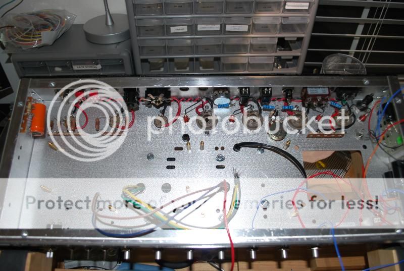
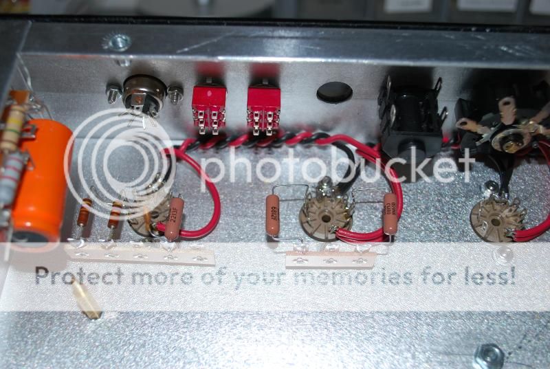
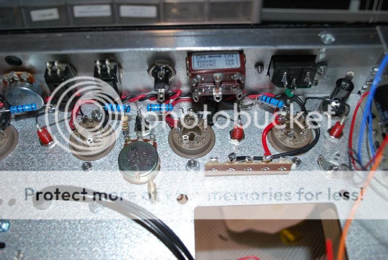
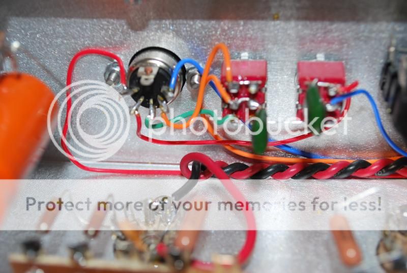
Here's the completed heater wiring, external bias points and the input resistors and other resistors for V1 and V2.

DSC_0105.jpg


DSC_0106.jpg


DSC_0108.jpg
 
stratotone":v1ukq3o2 said:
Here's a pic of an oooooold build of mine - I got a schematic off the web, hand built my turret board, punched all my chassis holes, sourced the parts from about 7 different vendors. It was before there were very many kits available - it's a Matchless Spitfire that I later added a boost function to.

ampguts3.jpg


Note how I did all the twisted wires nice and tight except for the wiring for the rectifier tube. DOH! hehehe.

One thing I did right IMHO is used different colors for cathode, B+ and signal wires between the tubes and the board. Looks cool and makes it easy to troubleshoot/tell what's going on fast. At least it did for me. :) I also grounded the preamp seperately from the power capacitors/transformers. made for lower noise. Oh, and be VERY sure that you keep the same polarity on your heater wiring for preamp and power tubes. Get one of them backwards and you'll have unkillable hum on your hands.

Pete

Sweet build Pete, I don't know if I would be able to build one if it weren't for kits and layouts. How did you manage to keep the heater wiring so tight when soldering everything? It seems that when I twisted the heater wires and when it came to soldering everything came undone and screwed up :lol: :LOL:
 
looks good, really interested to hear what their take on a Dumble sounds like ;)
 
merlop":20sy4sqw said:
I'm just wondering where the Hot Rubber Monkey goes... :D

The HRM controls are mounted on a board towards the front behind the treble / mid controls. Definitely a lot of stuff crammed into a small chassis. :)
 
Haven't updated this in awhile. I decided to change it up and build the Smartulator over the weekend which is the rack dumbulator clone. Pretty straightforward build. Doing the shield wires was kind of a pain in the ass at first since I was kind of doing it wrong. Pretty much the shield wire has to be stripped to show the shield, then you cut off a portion of it, then twist another wire around it and then heatshrink it. Haven't tried it out yet, but it turns on and doesn't blow up :lol: :LOL:

Someone on the Ceriatone forum shot this pic of how it should look.

index.php


Here's the finished Smartulator.

DSC_0109.jpg


DSC_0110.jpg


DSC_0111.jpg


Rest of the pictures can be found here.

https://smg.photobucket.com/albums/v344/ ... M%20Build/
 
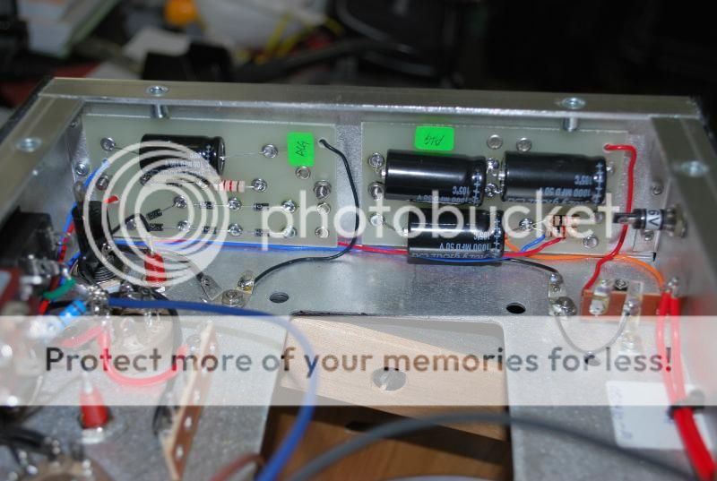
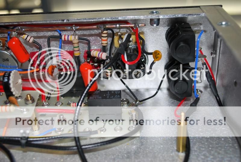
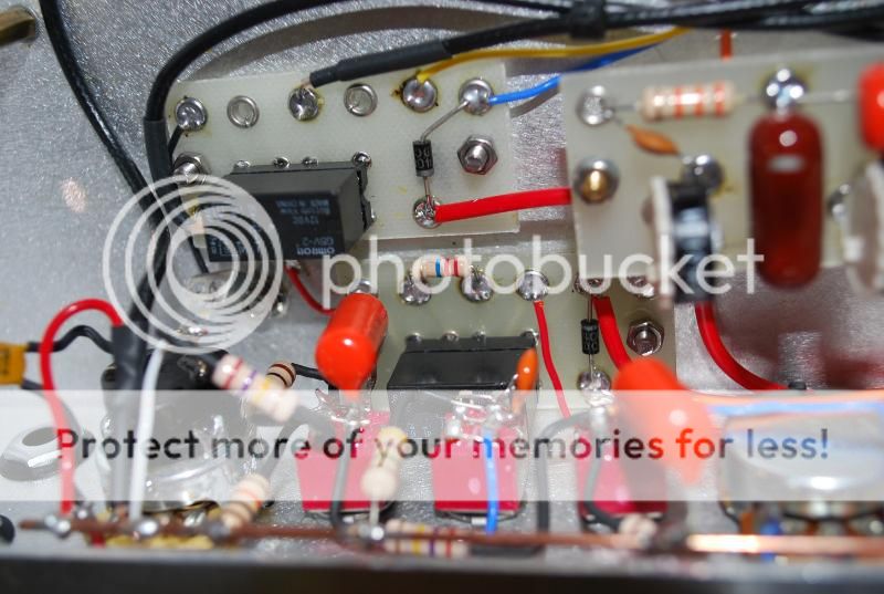
During the week I tackled the Tone Stack/Input Jacks/Relay boards and foot switching.

Footswitching is kind of tricky, since it's so damn small and the diagram is kind of all ass backwards, had to compare it back and forth with finished pics on their website. One thing I should have done was route the red/blue wire attached on the top of the footswitch since the beginning before I did the heaters. It's the power from the boards mounted to the side of the chassis.

DSC_0123.jpg


DSC_0125.jpg


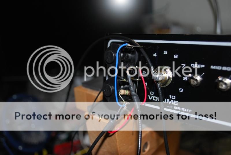
Here is how I did the input jacks, just mounted it on the outside of the chassis and wired everything from there. Way easier to do it this way.

DSC_0120.jpg


FX Loop is also wired up. Still haven't grounded it and it's missing a wire that comes from the main board.

DSC_0124.jpg


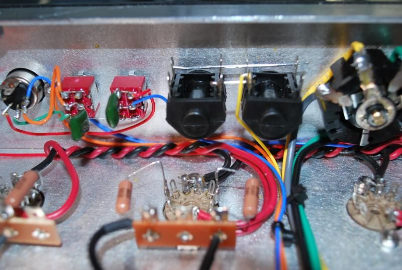
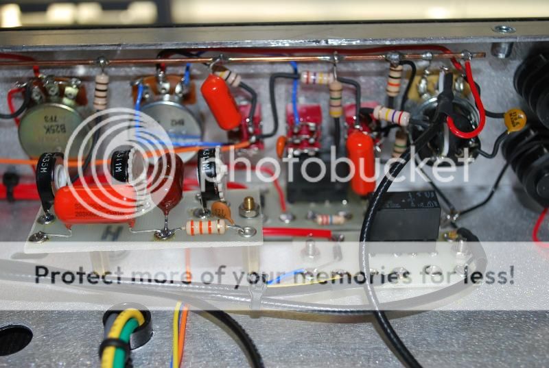
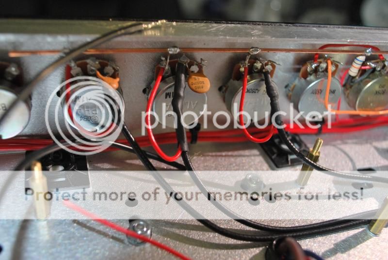
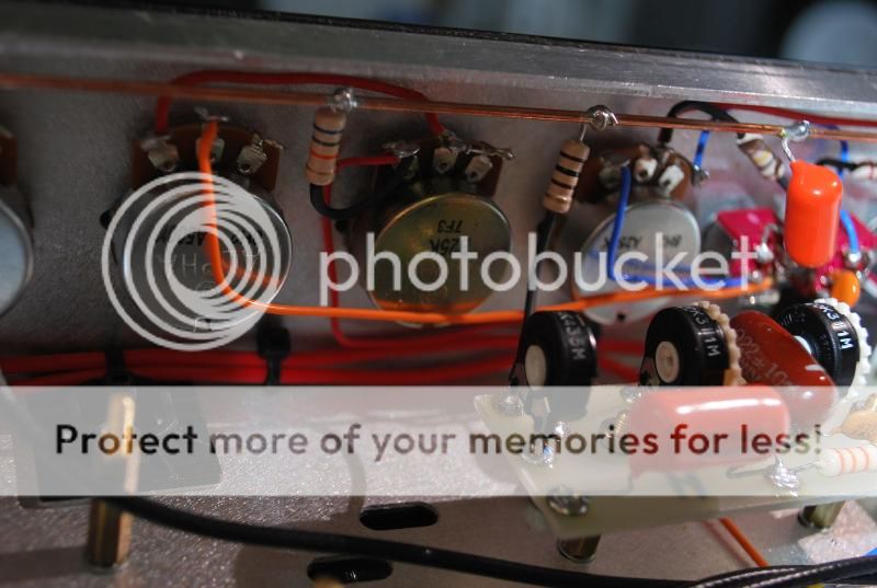
Fun part.. the tone stack and all the switches out front, I didn't bother mounting it on the outside because I figured it would be a pain in the ass to move all this back in. So just did this really slowly and carefuly. Used 1/16" heatshrink for the resistors and to mount the bus wire across the top I just used electrical tape to hold it up first, and worked from there. Also wired up the relay boards.. before you install the relay you should remove the middle DPDT switch or else it wont go in. Here are pics in no particular order.. :)

DSC_0132.jpg


DSC_0133.jpg


DSC_0131.jpg


DSC_0128.jpg


DSC_0127.jpg
 
Sweet job,awesome thread and this is bringing the gas hard core!!!!
 
Nice! I never really thought about building my own amp until I started reading more about it on this board. Now, I'm dying to pick up a kit and get to soldering.
 
jmgman69":2xvivhcu said:
Sweet job,awesome thread and this is bringing the gas hard core!!!!

Thanks! Definitely gets addicting building these, just want to build one of everything

jet66":2xvivhcu said:
Nice! I never really thought about building my own amp until I started reading more about it on this board. Now, I'm dying to pick up a kit and get to soldering.

Do it! :lol: :LOL: It's actually not too bad once you get started.

droptrd":2xvivhcu said:
That looks awesome. :thumbsup: Does it come with any instructions?

No instructions for the Ceriatone kits, there is just a layout available on their website and various pictures of the guts online. I just made this thread in case someone else wanted to build this amp. For a first build I would recommend doing the Metro ones, those are pretty much fail-proof, my first build was a Metro JTM45 which pretty much taught me some of the basics, this is only my second build though so I barely know anything about amps, I wouldn't be able to build a amp from scratch like Steve is doing :aww:
 
dstroud":rymstq7j said:
dude you got some mad skills! :thumbsup:

Thanks Darren :) All credit should really go to Nik @ Ceriatone for creating these Kits and making it somewhat easy for us newbies, I have no idea how he can wire up his stuff up so neat, I've just been using his pictures as a reference, who knows how shitty it will look if I didn't have his completed amp pictures as a guide.

So far today I wired the OT, the indicator light, OD trim on the back, added the 1K resistors on the power tubes and also the screen grid resistors. Will post pictures tomorrow night, working my way from the outside in and will be installing the PT and main board really soon. :rock:
 
Back
Top