Dann Valentino's Technical Mark IIC+ Reissue Writeup!

  • Thread starter Thread starter GJgo
  • Start date Start date
GJgo

GJgo

Well-known member
Over on Facebook on the IIC+ page, a member named Dann Valentino did an IN-DEPTH technical breakdown of the IIC+ reissue. He's not a member here (yet), but with his permission I wanted to post what he had to say over here as there's some good info. Here you go!! There's also quite a few good Q&As in the comments on the FB thread.

WARNING - Long and somewhat technical post.

Going off from Tony Batal's pics (thank you for posting these, mate!!) I will write what I see in a rather long post. Feel free to skip, correct me or disagree with me - I am just rambling nerd stuff. Those are purely technical observations and are not intended to put down the amp or how it sounds - if you like it - you like it and that's that. I'm only sharing thoughts on purely technical details - some people like to obsess over their "MoP settings, maaan", I like to obsess over technical details as an engineer and a designer. Some of the points I am including in this post can be considered as servicing cautions and what to expect/look for, others as general info.

Transformers:

Woodward-Schumacher Electric Transformers. GOOD! They went back to the original manufacturer. Makes me wonder what was the real reason (not the PR reason) for the short period not using Schumacher.

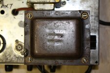
EIA606MS stands for "Electronic Industries Alliance". 606 is the manufacturer code for Schumacher, MS should be internal marking for Mesa. The 4 numbers after that are the date. In Tony's particular amp: the power transformer - 29th week of 2024, the output transformer - 35th week of 2023. That tells me that they are using their available stock of 542004 OTs and 561860 PTs. That version of the 562004 has been used in Mark V90, VII. The 561860 is used in the JP2C and in the Mark VII.

Interesting that they used the 562004 transformer and didn't order an earlier spec for the RI. The last transformer that is 1:1 to the original Simul-Class design is the 562003 (they just went to a new naming scheme). The 562004 they changed to a smaller lamination stack which did not change the tone that much in my tests(not pushing to full core saturation, tested with normal usage in mind). In the 562004R-1 (later Mark III Green Stripes, Mark IV Bs, later 2:90s) they removed two of the additional windings that define the original SimulClass transformer and that change definitely yielded a different character and impedance curves in my tests.

My main concern here is that I've seen a lot of later black chassis Mark IV Bs for instance, with the 562004 stamped on them, and after a few simple measurements it turns out it's technically a 562004R-1. I don't know why they did that tbh and not just keep using the 562004R-1 with it's proper name. After all they are two different designs. I actually haven't checked what's up in later models (Mark V, Mark VII) that also use the 562004 stamp on the transformers, but this raised my curiosity. Tony - could you test with a ohm meter to determine if the OTs on the RI and VII are true SimulClass like the previous 562003/562004 or it's technically a 562004R-1? No high voltage, no danger. I will shoot you a PM how to test it if you are down.

For more context - here's a real-world test between 562003, 562004 and 562004R-1 in the same amp.

Overall layout:

The original design is not too crowded or hard to follow, so personally I don't see the need to stack the preamp tubes like they did in the RI. There is enough space. If I would've changed the OG layout - probably put more space between a few know-to-act-up components, but keep the overall topology similar. As some of you know - component proximity/EMF/inductance is a thing and parts can influence each other easily. Even Randall Smith mentioned it the other day on his new YT series. I admit - this is cork-sniffing 101, probably less than 5% of differences if you will, but shouldn't a reissue be as close as possible to the original? I am now 100% sure the layout and/or lead dress are the causes of the reported oscillations. Strangely enough - the original amps (if taken care of and in 100% working condition), even though they can be considered a hot mess by most techs - don't have those problems. This fact and a video that I posted a few weeks ago proves that component placement/lead dress/layout can be a big part of how an amp behaves and to a degree - how it sounds.

Some stuff technically cannot be the same as in the OG (RoHS/CE compliance, availability ect), I've spoken about that even before the release, but the component layout is at the PCB designer's discretion and he can do whatever he wants (given it covers some basic rules and requirements). So the question for me is why not stick with the original, proven PCB layout that has millions of miles on it and just tweak from there. I think they could've spent a bit more time on the layout and this whole topic wouldn't be a thing - and frankly it's probably costing them a bit of revenue now.

They don't make the in-house PCBs like they did in the 70s and 80s. The old method actually required a lot more labor and time to make (manual drawing, masking, etching, drilling, tinning ect). After all, almost every PCB nowadays is manufactured with more automated methods, mostly in large, PCB printing facilities, most of them oversees, so manufacturing and prototyping today is ultra cheap and very fast - narrowing down the design for my SP2C V2++ boards cost me ~80EURO + shipping for two sets of prototype boards, arriving in 2-3 workdays. So for their level of operation and in-house capabilities, spending a few more days 100% nailing it - a no-brainer to me.

EDIT: By that I meant that they can very easily and cheaply make a few prototypes and nail down the layout and only then start producing the final boards with no "re-tooling" needed for every iteration. contrary to how it used to be.

The tube layout is reminiscent of what they have been doing since the Mark V (especially with the 25 and 35 variants).

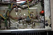
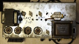
TBH, I don't see a single big issue with the preamp board, but rather a few small things that don't make much sense to me. Especially when copying a simpler design like the IIC+. One being the stacked preamp tubes, second would be putting the power supply/GEQ/preamp on one board, another - the weird criss-cross jumper cables for the heater filament supply. From my own experience designing PCBs - as soon as you run out of ways to use the two layers on a PCB and start jumpering with wires - you've put yourself in a corner and better go back and rethink some things. I'll give that kind of a pass though, since that there is a jumper cable in the original IIC+ as well (although for the Lead Circuit). The OG layout is not "TECHNICALLY" considered great (including the RP-11x boards), but it's been bulletproof for 40 years and as mentioned before - it's layout is somewhat contributing to the sound, so I would've just copied that in a heartbeat. Why open this Pandora's box, having to wait for this design to prove itself or show it's flaws instead of just betting on +40 years proven layout and build from there. For servicing purposes I would've never put the power supply and the whole preamp+GEQ (or in some other cases - the whole amp) on one board. I get why some brands do it (especially if led by non-tech minded suits) - micromanaging every cent spent, but I just wish they would've considered the guys like me that at some point will have to repair or work on those amps, hahah. In the attached pics I will include one of a Mark V:25 that required a PT change and the technician that worked on it needed to gut the whole amp to pull out the transformer. That's not good engineering.

(Continued in comments)
 
Components:

Here I will go a bit more technical. Almost all components seem good quality. Exceptions being some switches and small things like that - more on than some other time. Most notable ones to me:

◾️ Cornell Dubilier (CDE) Orange Drop 715P caps - good to see that they started putting 600V rated ones in the PI as 400V sometimes fail there. (Small rant -weirdly some are branded Mesa.. weren't we done with this? Why go with the hassle of rebranding a component instead of spending time on more important things...) The rest of the Orange Drops are MB 447 branded ones and looks like they are still 400V. BTW - when you hear your tone pots having a static-like/wind noise when turned (not the same as scratchy pots), but not loosing signal and OK when set - it's not a the potentiometer. Don't go for the deoxit. It's time to change the tone stack Orange Drops as they are leaking DC (and they pass only AC). I always put 716P/600V.

◾️ Alpha pots - Taiwanese, well known brand. Had some bad batches, but almost every manufacturer on the planet had at some point. Mesa has been using CTS for ages, but at some point they stopped making custom values/shapes for them and I assume that's the reason for the gradual change to Alphas. I prefer CTS and mainly use that in my builds and repairs. For the values that they don't manufacture push-pull versions, I buy a bunch more of the available push-pull ones and rehouse the needed value resistance track in the switched ones. But it costs more and takes time obviously.

◾️ Omron relays - as all their amps since the Mark V/reborn Rectos/ect. Good relays. I prefer using a different model for reliability when switching higher voltages, but in this case they are switching mostly signals - those are perfectly fine for that. The only thing concerning LDRs -vs- Relays, that I consider to change the response of the amp compared to the OG, is that the original LDRs (VTL5Cx) have some residual resistance in their ON state (in the ohms range) and that can influence things like the range of boost/cut on the GEQ. I explained that more in-depth in a comment not long ago and I will copy parts of it here:

OG Mark IIC and C+ (as well as Mark IIIs and IVs) use LDRs (light dependent resistors) to control if the GEQ is "on" or "off". The signal is always going thru the actual GEQ circuit and transistors (the driver board) and with the OFF/ON/AUTO switch you are only telling if the filters/sliders (5 LCR filters - inductor, capacitor, resistor) should be active or not via that LDR. When they are "off" the driver board is at unity gain on all bands and signal just passes through it (that's why some consider non-GEQ amps to be more dynamic - preamp signal straight into the PA). In other words - if the LDR is in OFF state, its photo-cell has high resistance (above 10M ohms) and the sliders are essentially lifted from ground/not active/not cutting-boosting. As soon as the LDR is in its ON state, the cell drops it's resistance to a few hundred ohms and that "activates" the sliders. Now, LDRs always have that "residual" resistance in their ON state - meaning they are never fully ON/connecting like a normal switch/relay is. ***I am mentioning switches because the Mark IIA/IIBs have the signal completely bypassing the GEQ via a DPDT switch - driver board and sliders are all bypassed so the signal from the preamp is directly fed to the power amp, causing some volume differences (not in unity gain) - the reason why they later decided to keep the signal going thru the driver board at all times and then switch ON or OFF only the filters/sliders.*** If the switching LDR has drifted with time to a higher residual resistance than expected (or the LED inside is getting weak/the low voltage supply of the amp is acting up), it essentially lowers the effect of the sliders. This is the main reason why no two GEQs are completely the same when it comes to boost/cut dB range.

Using a relay for the GEQ is a good thing as they make a straight contact/don't have resistance, so they don't drift with time like a photo-cell or LED inside a LDR, thus the GEQ responsiveness stays constant. Another good thing about relays is that they switch instantly (well, in the milliseconds, but for our purposes that's instant). LDRs have a curve that ramps up/down to the final ON or OFF state. Ambient temps also can slightly affect the ON state resistance and the time getting there. This is why in some OGs/Mark IIIs that have drifted LDRs you can hear volume jumps/ducking when switching between channels - the LDRs that re-route the signal take different amounts of time to full go ON or OFF . So I would consider using relays a good thing for consistency and reliability. In more complex amps (modern rectos, Mark Vs and later) relays can introduce pops and to remedy that - a mute circuit is used. A circuit that shunts the signal to ground for the super short time it takes the relays to switch, eliminating the pop. It's like very, very rapidly turning the master to 0 and back up. In some amps that mute circuit has been the culprit for intermittent issues, but generally not a big deal. In the RI, I see a few JFETs (J175) that probably are used for that, I will look into it more at a later point. The only spot that relays will make an audible difference is in the the Treble Shift (Lead Fat on Mark IVs). In easy terms - the few hundred ohms left in the LDRs actually can affect the cap being switched in and out and how it is affecting the circuit. With a relay, the cap that is being switched won't be influenced (consistent from amp to amp); in LDR switched amps - the cap always will be influenced by the residual photo-cell resistance and that will shift the freq. point and affect the effectiveness slightly (depending on the amount of that residual resistance). If in theory we assume all LDRs in the world are 100% in spec and don't experience any value drift (known residual resistance) - there would be a consistent, baseline effect on the cap/treble shift circuit that would be easy to compare to a relay (without any contact resistance). Now adding back the tolerances, drifts ect - its just one of the million small things that start to explain why there are no truly identical sounding amps. There is a very simple way to make a relay act like a perfect, 100% in spec LDR, but that's a story for another day as I am getting to much into the minutia.

◾️ J175 JFETs - will investigate more, but it seems like they are used for mute circuit for the switching, Reverb on/off (shunting it's signal to ground, I actually use a similar method) and a few other small things - just at first glance.

◾️ Ribbon cable: It seems like its carrying the signal out of the PI, the Bias supply and potentially the B+ HV, but cannot confirm with 100%. Don't quote me on that - will investigate further at some point. The only issue with this type of connections historically has been the actual connectors failing and sometimes melting with high current loads. They don't seem to be carrying high currents in this amp, so nothing to worry about.

◾️ The PCBs look like they have been manufactured by a well known Chinese factory (I could be wrong), and that's good. The trace width and placement in some spots is what's concerning to me, but Mesa has been using thinner and wimpier traces for a while now. It's kinda funny to see a 3W resistor soldered to 0.5mm or smaller trace.

EDIT: The most important thing here to focus on would be the actual design of the PCB and not so much where it was manufactured. With a few decent machines almost everyone can create great PCBs. That said - any professional facility/well geared shop nowadays will be top-notch for this kind of THT equipment. Multi-layer, ultra-precision +/- 0.05mm PCBs like in fine electronics is a different story.
 
Power supply and filtration:

Here is where I see the biggest difference and frankly - hear the biggest difference from all the demos and vids so far. The filter caps and the overall tightness and graininess of the amp.

◾️ There are two 220uF/350V main filter caps in series that equals to overall 110uF filtration. They are KEMET-made (same as the small, yellow tantalums), ESK series - reputable US brand, now made in Taiwan. The thing to note - that's the correct filtration for the class A/B 60W and 60/100W IIC+/Mark III models, not the SimulClass ones. The SimulClass IIC+ and Mark IIIs have additional 2x220uF caps, parallel to the already existing ones (four 220uF caps in total) that bumps the overall filtration to 220uF. If you look at OG DRG pics - the two caps that are underneath the power supply board. More filtration = stiffer, tighter, bolder power amp and sometimes more headroom/few dB louder. In the Mark IVs and later SimulClass amps, they used only 2x 220uF in series (overall 110uF), so it obviously stayed like that since the Mark IV. I am planning on making a video on showing the actual differences between more/less filtration (playtime + real-time oscilloscope measurements), but still not sure how to go about it. Essentially think of it as modded -vs- original old Marshalls - Cameron was putting huge filtration to make the amp super percussive and tight, but almost too stiff to play; guys like Friedman prefer original Marshall specs even in more gain-ier, modern iterations as it yields more sag, sounds "browner", forgiving, more EVH as some say. Some even go under normal Marshall specs to put more sag and character in the amp, JTM-like.

◾️ The next high-voltage nodes are filtered with 33uF/500V, 4 in total, so as the OG there. They are NIC brand, NRBCX series - lesser known Japanese brand, budget friendly, not as premium as Nichicon for instance.

◾️ The GEQ supply seems to be filtered with 150uF/100V IC (Illinois Capacitors - most of you know how I feel about the brand, but here they are fine) instead of the 220uF in the Mark II, III and IVs. Should be fine, but now I am interested to test out the effects of that.

◾️ Bias caps should be 47uF/100V, but I cannot see what they used here. No reason for them to change values thou, can't make out the brand, moving on.

◾️ The additional small caps are the filtering the 12V DC regulator (supply for the relays, JFETs and fan). This circuit is often used, simple design - a LM2940 12V regulator, 2200/4700uF for Vreg IN (it seems to be an IC cap), 15uF/22uF for Vreg OUT (Kemet 25V tantalum) = stable, clean 12VDC supply. Good on them for not going back to the rather weird switching (and it's supply) in the original Mark IICs/Mark IIIs.

◾️ *This next point concerns all modern Mesa amps, not specific to the RI: The only technical issue with the filter caps is that they are all radial ones (the vertical type) without an easy access for servicing them. That requires the board to be lifted, at least partially (in some amps - completely) to change them. In other words - disassembling other things that don't actually need to be touched. Also if the caps start to leak - you won't be able to see until the amp starts acting up and potentially damaging the board/traces. They can leak at any time - new, old - it happens. For this reason, power supplies are generally better put on a separate board, so you can work in a modular fashion without the need to disassemble 80% of the amp to change a 2 components. And if they leak and cause major PCB/component damage - it's contained to that board only. On the other hand - the good thing about using radials instead of the classic axials - future proofing. Axials have been phased out with modern manufacturing and are expected to be completely extinct in the near future. Back to the RI - TBH, it won't be a nightmare to service like the Mark IVs, Vs, JP2C ect, but still the layout is weird to me. I can rebuild 80% of the preamp on a IIB/C in half a day, this could take days.

Further notes:

◾️ The whole power section is hardwired in Pentode.

In other words - the outer, Class A tubes are wired in Pentode instead of Triode like on the OG. People that have played the Mark IV and switched between Triode/Pentode know how it affects the response and tone. Fatter, louder and bolder as they are more efficient in Pentode. BTW - this layout looks easy to mod for a Triode/Pentode switch.

◾️ The EL34 question - so far I don't see an obvious reason why they said EL34 in the Class A sockets will void the warranty. Since EL34s pull more current from the filament heater supply - that could be a reason if the PT and it's heater winding is not rated (big enough gauge) for more current draw. Generally speaking PTs should be rated for more than the amp requires to insure stability, but I am not familiar with this model PT at this point.

PS.: Or they changed the bias point. Cannot tell for sure as I need to test and measure the amp.

____________________

So far my main concerns are mainly about reliability and servicing, as with every new-ish Mesa. Don't mean to offend any loyal brand fans - it's a known fact that they are temperamental and not as sturdy as some claim.

The "tone affecting" changes here and there - they take 2nd place IMO. The amp seems to be on par with everything they have been putting out in the last 10-15 or so years, similar methods, similar cost-cutting measures. So not bad, but not great. Again - not talking about how it sounds. With this particular simpler design it could've been way better for the same amount of RnD, investment and cost. By I don't work for a Gibson-owned brand, so what do I know, right?

Seeing how things have gone the last few years with tech support (especially outside US) - let's see what happens when they are out of warranty and how Mebson reacts when owners look for help. I have some infuriating stories to tell from the past 2 years, but that's for another day. I just hope my fellow techs have strong will and nerves of steel. Otherwise there is no reason why the amp shouldn't sound good. Is it 100% like the OG? Nope. Does it matter? Up to whoever pays the bill.

______________________

I hope this was helpful and I hope I didn't offend anyone. Again - please correct me if I missed something and feel free to disagree with me on any of the points - I am loyal to the art of amp building, not a certain brand, so I tend to share my experiences and opinions without reservation... and Mebson already hates me. :p

PS.: Btw - for the couple guys that asked - it can be C++ modded, wink-wink.
 
Dann Valentino-

Filtration should be the biggest thing when it comes to tightness between an OG DRG and the RI.

Not sure about the OT, the lamination as showed in my video is the least contributing factor in normal playing conditions (if you are not pushing the transformer to full core saturation). The internal winding/wiring was a big jump and I have to runs some tests to see if in those new branded 562004 OTs the internal wiring is a true SC transformer or a pseudo one like the 562004R-1 (which I fear it is).

Let me point out that the RI is fully hardwired in Pentode. The stock OGs have the Class A sockets running in Triode mode which is less efficient = leaner in the bass, lower output, but easier to drive and produces more harmonic distortion (THD).

So it's not really easy to compare a stock OG DRG with a stock RI.

So far Tony Batal can be the most helpful answering those tonal questions, as he has a DRG wired in Pentode, so the comparison will be more apples-apples.
 
Last edited:
Jacob Cunningham-

First and foremost, thank you for taking the time to write this and share your expertise. Very interesting read. Second, how do know it’s all hardwired in pentode? Is that something that can be seen just by looking at the guts? I wonder if Mesa would add a pentode triode switch

Dann Valentino-

Jacob Cunningham It's an easy thing to spot, yes. It also can be narrowed down by the specs announced, so I knew it was a Pentode amp since they showed the specs, now I can confirm it by checking the guts. I will my reply to a similar question:

-That was expected as soon as they announced it as 25W in Class A. Looking at the pics now it's 100% confirmed.

For 2x 6L6GC running in Push-Pull Class A in Triode Mode you can expect 10-15W. Same but in Pentode Mode pushes the efficiency up and you can expect 18-25W.

Those are rough numbers and actual clean RMS Output will be different depending on many factors that can affect the power output - Plate Voltage, Load, Bias, Screen Voltage in Pentode.. the actual tubes.
 
Last edited:
Miles Ramirez-

Good insight one the LDR on state in the GEQ. It must be the reason why the OGs dont sound as modern V as the later mark series.

Dann Valentino-

Miles Ramirez Thank you! Part of the reasons, yes. There are some components in the originals that are now discontinued and replaced with alternatives, some technically better. All these small changes contribute to different behavior of the later GEQs.
 
Kevin Pittsey-

Thank you for your insight. Are the LDR’s the reason there will never be a true RI? And why each OG sounds different? Good ones and great ones?
Also, I am lucky enough to have an original 84 C++ one of 5 known that the current ++ mod derived from. I would be curious of the difference between the original ++ to the modern mod technically.I can see the difference because I have/had both. And can hear the sound different for sure. Pm if interested.

Thanks again for your insight.

If it’s a DRG you have to be able to use EL34’s in the outer sockets period! Without warranty issues..6L6’s & EL34’s sound different! Together it’s magical..Isn’t that what simulclass means?!
🤣
😜


Dann Valentino-

LDRs in general are not obsolete - the Vactrol VTL5Cx series are because they do in fact don't comply with RoHS and CE/EU standards. They have Cadmium as mentioned by Alex and use older manufacturing processes.

There are modern replacements and alternatives out there. Some people use chinese copies - they are good, but have wide tolerances, so you have to buy 10 to narrow down 4 or 5 to be in spec. Another option that people use is the NSL32 by Ad. Photonix - good, fast but kinda fragile and wimpy IMO. I am testing another solution that will be a drop-in replacement and act as a LDR, but be way more reliable and stable with time. I will definitely post about it when I have everything down.

LDRs are not the sole reason why something is not like another thing. It's just a component out of hundreds. It can affect things like mentioned, but that doesn't mean an amp cannot be recreated without them. The amp release I am working on for late 2025 will be an example of that.
Since you have an original C++ - we need to talk. I will PM you one of these days. I am working on an archive/database for everything between the Mark IIB to Mark IV.

What do you mean by the "modern ++?". There is only one ++ mod that could be fixed or switchable. That's it.
As for SimulClass - that doesn't have anything to do with tube type (6L6GC or EL34). SimulClass is, as the name suggests, a configuration that runs two operational classes simultaneously - Class AB and Class A.

The option to put EL34s in the outside, Class A sockets is a byproduct of the way the bias works in a SimulClass configuration.
***EL34 is a 25W tube (plate dissipation), but requires more current for the heater filament. This puts more stress on the power transformer. As mentioned in the post - the reasons why Mesa voids the warranty is probably because of not over-speccing the PT for that OR running the bias at a different point that puts the EL34s out of safe range. I have to have an amp in front of me to be able to confirm IF it's fine to run EL34 and Mebson are just playing.

Kevin Pittsey-

Dann Valentino
The ++ in the OG best described as certain components from the 80’s spread out over the board and mentioned time consuming to mod. The ++ he does now along with better tech is actually part of the mid pot now. Since he had so many request for it. He simplified it. Just what I can tell from having the two next to each other and seeing the difference. And kind of trying to trace it the best a non amp tech can.
😂
😜
 
Last edited:
Dann Valentino-

Triode to pentode is a very simple thing - in simple words - Triode mode is wiring the Anode/Plate to the Screen Grid (G2 or Gs) via a resistor (470R in our case). This essentially disables the Screen Grid and make the tube behave like a triode. It lowers the output of the tube and it's efficiency, but sounds rounder and warmer. Mixing that with the Class AB inner tubes that stay in Pentode mode just broadens the spectrum so to speak, add something different. Like adding another make/model mic on your cab alongside the main one.

Pentode is running the Screen Grid as a separate element, utilizing the whole tube (the whole pentode) powered by a separate filtered node on the power supply, always through a current limiting resistor in the range of 470R to 2.2K or more. Now both the anode and the screen grid have different supplies and different voltage on them. In Pentode (full tube) mode you utilise the full gain and power of the tube. (Gain as in signal amount, not as distortion - I realised that tech's use the word gain a bit differently than guitar players and musicians, hahah). It provides the maximum power output the tube can push out, so more clean headroom and sounds more dynamic and punchy.

Switching between the two is actually very easy and requires moving 4-6 connections. Hence the switch in the Mark IV.
As for Tony's Mark IV OT equipped amp - it probably had issues/blown with the previous one and both 562003 and 562004 are perfect replacements. 562003 being identical to the original one but under different naming scheme.

If it's a 562004R-1 (that could be stamped 562004 as seen in some later cases) then this will have a decent impact on changing the character/feel of the amp and best to seek another OT that is a true SimulClass transformer. The video on my channel about the 3 aforementioned versions outlined all you need to know. I am working on follow up to the original vid, showing you how to do a simple check if it's a "true" SimulClass transformer with all four windings present, or just two windings with four connections.
 
Interesting, and a very cool write up from an engineers perspective. But, one thing he mentions stands out as actually 100% opposite being true...when he mentions Cameron and his filtering, making his amps stiff and hard to play...that's 100% false. I've had 10 and every one was super easy to play, and most refer to the feel as 'greasy'....no other modded Marshall quite has that. The closest is actually the factory 86-90 JCM 800 2210. Great easy feel.

But ultimately, the C+ RI is well done, and it sounds like Gibson could have done it even better for not much extra effort.
 
Carlos Perez-Silva-

What's your opinion on changing all the orange drops to those tighter spec/higher voltage rated Panasonic orange caps? Is something like that worth doing and would that change the tone at all? Improve etc.?

Dann Valentino-

Carlos Perez-Silva Personally I haven't tried those so I can't tell you much. 715Ps have been a staple of a few legendary amps - Marks, SLO, Wizards. I sometimes prefer using 716P as an upgrade and since they have oval profile - they can fit in tight spots when bumping to 600V. I don't think 715P/716P have too big of a tolerance window and still haven't seen a new/good cap way too out of spec so I wouldn't worry about it much. They also don't need to be 100% of the value written. 5-10% +/- here and there is completely fine and gives the amp it's own character. If let's say a 470nF cap measures 400nF - then, yes - I would change it as it's making too big of a change. If it's measuring something like 460nF - it's fine. If all components were 100% the same with no tolerances (virtually impossible) the amps would actually start to sound identical. Super tight, precise tolerances are goals in computer systems. I think the same reason why you prefer your amp over a Quad Cortex profile of it applies here.

There is one improvement when installing/replacing film caps thou and I will be making a video about it very soon.

In other amps and studio equipment I often use WIMA as a precise and sturdy part when I need polypropylene or polyester caps. For instance Peter Diezel (Diezel Amps) and my friend Gregg from Garland Amps are also both fans of them.
 
Thanks for that. What I came away with is:
Compared to the OG, it has less filtering so it's not as tight and the Class A in Simul is not Triode...
These things matter..
True, confirming the RI is full pentode makes me personally MORE interested as I don't care for Triode. I wish they would have done a switch though as triode is probably more popular.
 
Transformers:

Woodward-Schumacher Electric Transformers. GOOD! They went back to the original manufacturer. Makes me wonder what was the real reason (not the PR reason) for the short period not using Schumacher.

EIA606MS stands for "Electronic Industries Alliance". 606 is the manufacturer code for Schumacher, MS should be internal marking for Mesa. The 4 numbers after that are the date. In Tony's particular amp: the power transformer - 29th week of 2024, the output transformer - 35th week of 2023. That tells me that they are using their available stock of 542004 OTs and 561860 PTs. That version of the 562004 has been used in Mark V90, VII. The 561860 is used in the JP2C and in the Mark VII.

(Continued in comments)

He forgets to mention, the reason Mesa went to Magnetic Components, is Schumacher moved manufacturing to Mexico and Mesa at the time wanted to stay American Made.
 
Last edited:
i'd like to hear a quick cliffnotes on the infuriating stories about mesas customer service in the last 2 years.
they have my mark IVa rn...

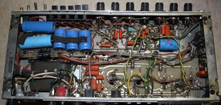
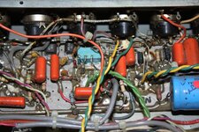
also, i had an original 11/84 c++ i took detailed pics of the boards:
if my memory serves me right, i got this for like $500 or something like that on ebay one day in 2010. it was just listed as "mesa boogie amplifier" or something like that with a stupid low buy it now, and i was in the right place at the right time. Just like the day i walked into GC and got an original white c+ long head and matching cab for 2699 together in the mid 2010's. Thank god i had my credit card on me that day lol. All have been sold long ago because i'm a greedy cunt... but i digress.

it came in an old mark IVa combo cabinet, and some of the filter caps date 1988, so who knows, maybe the mod was done in the late 80's or something. no writtings on the inside about a c+ -> c++ mod. just the ++ on the back above the cord. i don't think the mod was switchable on this one.
 

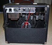
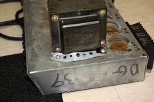
Attachments

  • IMG_8864.JPG
    IMG_8864.JPG
    124.8 KB · Views: 24
  • IMG_8855.JPG
    IMG_8855.JPG
    1.3 MB · Views: 26
  • IMG_8847.JPG
    IMG_8847.JPG
    1.3 MB · Views: 23
  • IMG_8849.JPG
    IMG_8849.JPG
    1.4 MB · Views: 24
  • IMG_8850.JPG
    IMG_8850.JPG
    1.2 MB · Views: 23
  • IMG_8856.JPG
    IMG_8856.JPG
    125.5 KB · Views: 26
  • IMG_8857.JPG
    IMG_8857.JPG
    1.4 MB · Views: 22
  • IMG_8861.JPG
    IMG_8861.JPG
    68.2 KB · Views: 23
Last edited:
the 2205 and 2210 sound KILLER when they work properly. fucking channel bleed and other weird issues kinda ruined them for me though.
If you hold firm on only grabbing a very late 86-90 version it'll be golden. All the circuits do have some channel bleed; there's a couple caps that can be changed to higher values to help this though. But, I've only treated them as 1 channel fire breathers, by simply turning the normal ch controls all to 0.
It isn't much of a clean anyway; dirty clean at best.
Also, the later versions have the good FX loop. Earlier ones are hit/miss.
 
Back
Top