Finished my first build this week

  • Thread starter Thread starter ibzprestige
  • Start date Start date
I

ibzprestige

Active member
Bought the Mojotone British 50 Watt Master Volume kit, recieved it last Saturday and finished mid last week. I’ve done mods before but this was my first from scratch build, It was a lot of fun. I know some of the longer wires can be cleaned up, but there’s absolutely no noise when it’s on and turned up, so I’m in no rush with cleaning that up. Now looking for some little tweaks I can do to make it a little meaner, anyone have any suggestions? It is a 1978 JMP 2204 circuit.

IMG_3627.jpeg

IMG_3646.jpeg
IMG_3647.jpeg
IMG_3648.jpeg


Wiring diagrams:

https://www.mojotone.com/Amp_Kits/British/British_50W_1978_2204_WD.pdf
 
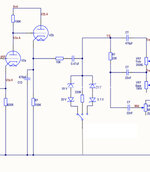
I like 2k7 with 0.68 bypass caps on both sides of v1. Might also try getting rid of the plate snubber, a 33k to the first grid and a 150k on the first plate. Maybe some diodes too, they’re pretty easy to install on a switch.

Check your B+ to the pre as well. Might try bumping those voltages up to 2203ish specs.
Thank you, I will clip in some of those values and mess with it.

On this circuit where would I wire in the switch for clipping? I did the Headfirst Origin Jose mod with the 3 way switch, and that amp is pretty angry.
 
Thank you, I will clip in some of those values and mess with it.

On this circuit where would I wire in the switch for clipping? I did the Headfirst Origin Jose mod with the 3 way switch, and that amp is pretty angry.
I do it like this… basically just the diodes tied in off the 100k with a switch to ground.
 

Attachments

  • A4F3B8C1-752B-4931-8A4A-3DB7762D0DE6.jpeg
    A4F3B8C1-752B-4931-8A4A-3DB7762D0DE6.jpeg
    291.3 KB · Views: 70
I do it like this… basically just the diodes tied in off the 100k with a switch to ground.
Perfect, thanks!

I clipped in a 3.3k resistor and .68 cap to the stock 10k on the one side of v1, and wow, already a huge difference in gain and aggressiveness. I have a little bit of hiss now though with this set up, could be due to it not being soldered in.

IMG_3667.jpeg
 
Nice, I didn’t see it in the earlier pics but you should try some shielded coax on both grids of v1. That should help with noise when adding more gain.
Thank you guys for the input, I truly appreciate it. I do have some rg174 shielded coax here, so I will get to installing that and cleaning things up.
 
Now looking for some little tweaks I can do to make it a little meaner, anyone have any suggestions?
Awesome build! I recently got one of these and am going to be building it soon. Did you build it straight from the wiring diagram or make any changes?

The first thing I am going to do after I finish mine and play it for a while are these mods:
 
Awesome build! I recently got one of these and am going to be building it soon. Did you build it straight from the wiring diagram or make any changes?

The first thing I am going to do after I finish mine and play it for a while are these mods:

I built it straight to the diagram. I also bought the components to do the JEL mod, I just wanted to have some fun with it before I went all out with the mod and make sure everything was working.

I did end up putting shielded cable on the input and gain pot to V1
 
Bought the Mojotone British 50 Watt Master Volume kit, recieved it last Saturday and finished mid last week. I’ve done mods before but this was my first from scratch build, It was a lot of fun. I know some of the longer wires can be cleaned up, but there’s absolutely no noise when it’s on and turned up, so I’m in no rush with cleaning that up. Now looking for some little tweaks I can do to make it a little meaner, anyone have any suggestions? It is a 1978 JMP 2204 circuit.

View attachment 297867
View attachment 297870View attachment 297873View attachment 297876


Wiring diagrams:

https://www.mojotone.com/Amp_Kits/British/British_50W_1978_2204_WD.pdf
That is bad as fuck
 
You need to reflow all of your solder joints. Every one of them are cold soldered. The solder should flow into the joint and adhere. You need around 600 deg F.

Your solder iron also compromised one of your 470pF bypass caps across a 470k resistor. You should replace it as it will be prone to fail short.
For someone getting ready to build one of these would you recommend any changes to the wiring diagram?
 
For someone getting ready to build one of these would you recommend any changes to the wiring diagram?
I’m a big advocate for improving the stock ground schemes. Every pot should reference a starred ground attachment and not the chassis ground or potentiometer body like a stock amp does. As much as people hate on Larry and for good reason, his 5 star grounding scheme is what should be followed. You want to cut down on ground loops inside the chassis especially once you start going down the path of modding for high gain.

For a novice I suggest learning how to install coax correctly with only one side referencing ground and knowing where they should exist. Ask questions along the build.
 
You need to reflow all of your solder joints. Every one of them are cold soldered. The solder should flow into the joint and adhere. You need around 600 deg F.

Your solder iron also compromised one of your 470pF bypass caps across a 470k resistor. You should replace it as it will be prone to fail short.
I did reflow everything after I got it all working and modded with the JEL spec. One question, I did that mod and installed coax on the input and gain pot, input is grounded to the ground lug of Jack, and gain pot is grounded to back the pot, one side only on each. I seem to now have a ground loop. And I didn’t before with the standard pvc wire. Any idea what I should look at to remedy it?
 
Awesome build! I recently got one of these and am going to be building it soon. Did you build it straight from the wiring diagram or make any changes?

The first thing I am going to do after I finish mine and play it for a while are these mods:

I ended up doing this spec last night. It sounds really great. Definitely recommend trying it out.
 
Looks great man. It's a slippery slope though lol. You'll be planning your next build before this one is over.

I wouldn't worry about the wire lengths. If it's quiet, there is no need to mess with it
 
Looks amazing man. :cheers:

Heyboer tranny's?
Thanks and yep!

Looks great man. It's a slippery slope though lol. You'll be planning your next build before this one is over.

I wouldn't worry about the wire lengths. If it's quiet, there is no need to mess with it

Thank you! I’d be lying if I said I didn’t already have parts coming for a new build, hahaha
 
Back
Top