I am finally going to remove the .047uf 600V death cap off the polarity switch in my 72 Marshall

  • Thread starter Thread starter harddriver
  • Start date Start date
H

harddriver

Well-known member
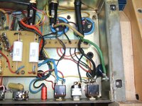
I've read some differing views on this and wanted to ask some questions, I have researched some post online about vintage Marshalls and the death cap and intalling ground plugs on them. I have already cut the old cord out and have a new 16/3 ready to go in. The amp did have a 3 prong grounded plug with the black(hot wire) feeding the input side of the bottom lug of the polarity switch and has a jumper wire over to the + side of the power switch, the white neutral wire feeds the mains fuse and the green is grounded to the chassis but the .047uf death cap is connected to the center lug of the polarity switch. The top lugs of the polarity switch has a light blue wire from the power transformer soldered across the lug to a yellow wire that connects to the output lug of the mains fuse.

Some say just clip the .047uf death cap out and you are good to go and leave the polarity switch as is wired. I will unsolder the death cap cleanly regardless but I may want to move my PPIMV into the old polarity switch hole so I can re-install the speaker jack I pulled out for the PPIMV years ago so I would need to unsolder the blue and yellow wires from the upper polarity lugs resolder them and apply some heat shrink tubing thus allowing removal of the polarity switch all together. But if I were to keep the polarity switch in for aesthetic reasons then the blue an yellow wire just remain soldered across those upper lugs.

We will leave the polarity switch in for the sake of this discussion. Unsoldering the .047uf death cap and leaving the blue and yellow wires soldered across the top lugs of the old polarity switch.

Here is where this other method I came across online differs from the first one and how the amp is wired right now. It states the the black(hot ) wire must be connected to the input lug of the mains fuse holder and the white neutral must be soldered to the power switch input lug and then of course green wire to the chassis ground lug as seen in the current pictures with the .047uf death cap removed of course.

Usually I would wire black(hot to input side of the power switch) and white(neutral) to the mains fuse as I have done on all my builds so far.

So which is the most correct method for the hot, neutral connection? Black(hot) to fuse/White(neutral) to power switch lug or Black(hot) to power switch lug/White(neutral) to fuse.

Of course green to chassis ground for both scenarios.

I have attached some pics as the amp was done by a tech before I got the amp and I just left things be. It was time for a new power cord and seen it still had the death cap in it so I figured it was high time to pull the death cap out.
 

Attachments

  • DSCF3193.JPG
    DSCF3193.JPG
    934.1 KB · Views: 74
  • DSCF3194.JPG
    DSCF3194.JPG
    917.6 KB · Views: 42
Always fuse hot, never fuse neutral. If you fuse neutral and have a switch failure that still allows black to stay live, a person can get shocked conducting black to ground through their body.

Black wire to fuse immediately and then to power switch. Neutral to other side of mains switch (mains switch should be appropriately rated DPDT). Green soldered to a steel tab to chassis ground with the steel solder tab having a steel lock washer. Don’t use aluminum tabs to solder copper wire - it’s a fire hazard from expanding and contracting disassociated metals. Technically code states green should be dedicated to its own steel solder tab/lug.

Cut the death cap and leave the polarity switch but have it disconnected for aesthetics only.
Thanks for looking over this glpg80, I appreciate it. :2thumbsup: Fusing the hot(black)120ACV wire does make sense and that's what I see when I watched some death cap videos regarding Fender amps, the techs were fusing the black(hot) wire.

I even consulted my old Metro amp build instructions and it clearly shows the Black(hot) 120ACV connected to the switch and the white(neutral) to the mains fuse. I had not really questioned it until now.

Is this something Marshall did in the past that wasn't technically correct? I can't imagine George Metropolous would send out thousands of instructions and no one ever called it out, I just checked all of the instructions for the Metro 50, 100 Superleads all are running the black(hot) to the switch and the white(neutral) to the mains fuse.

The JCM800 instructions with the IEC connector does show the hot leg(black) going directly to the fuse first then another black wire is routed up to the mains switch along with the neutral wire to the other lug on the JCM rocker switch exactly as you describe.

Here is a pic of a 1975 JMP with black bat switches
1735412783569.jpeg

1735416524817.jpeg

1735413195529.gif


So if I were to remove the polarity switch all together then the robin egg blue wire from the PT winding and the yellow wire coming from the mains fuse would then be moved over to the upper lugs of the main power switch. I know the black wire from the PT is for the 120 VAC selection. What is that robin egg blue wire from the primary side of the PT that shows 0 V according to a Drake wiring ID and why is it connected to the yellow wire coming from the mains fuse completing a 120ACV fused circuit???? Sorry...........I don't mean to be a bother..... I just want to understand why this amp was wired the way it was. The hot does appear to be fused on the schematic with the IEC connector but Marshall appears to do the opposite with their amps prior to using the IEC connector?????? WTF?

So every Marshall amp that has the hot on the switch is a potential shock hazard if the switch fails, that's probably alot of amps out there wired like this.:shocked:

I do think I want to remove the polarity switch all together to make room for a PPIMV which is why I am asking where to move the robin egg blue and yellow wire are seeing 120ACV on the polarity switch as wired and then 120ACV if moved over to the mains switch. From what I can see they would be moved to the upper lugs of the power switch as I seen in that pic of 1975 JMP with the same PT.

Drake PT 1202-324/7 Wire Colors:
Mains VAC Primary;
240 Yellow
220 Orange
120 Black
0 Blue
Secondary;
High VAC;
Red
Black CT
Red
Heaters 6.3 VAC;
Black
Brown CT
Orange

Here's a 79 2203...
1735416933074.jpeg
 
I’m just saying what’s technically correct and the way I wire amps. I don’t really care why someone does something unsafe or wrong - I only care that people do it correctly. I’d assume at some point there were requirements to get UL certifications which prior versions didn’t have.
 
I’m just saying what’s technically correct and the way I wire amps. I don’t really care why someone does something unsafe or wrong - I only care that people do it correctly. I’d assume at some point there were requirements to get UL certifications which prior versions didn’t have.
I agree fully, I had just never questioned it before. I have an NOS black bat switch coming yet to replace the metal one in the amp so I have time to map out exactly what I am doing

What exactly is the 0V blue wire coming from the primary side of the Drake PT then and why is it connected to make a closed circuit with the fuse circuit and receiving 120VAC?
1735419644690.jpeg


I do think I want to remove the polarity switch all together to make room for a PPIMV which is why I am asking where to move the robin egg blue and yellow wire are seeing 120ACV on the polarity switch as wired and then 120ACV if moved over to the mains switch. From what I can see they would be moved to the upper lugs of the power switch as I seen in that pic of 1975 JMP with the same PT.

Drake PT 1202-324/7 Wire Colors:
Mains VAC Primary;
240 Yellow
220 Orange
120 Black
0 Blue
Secondary;
High VAC;
Red
Black CT
Red
Heaters 6.3 VAC;
Black
Brown CT
Orange
 
Blue is the other side of the switch that matches up with neutral. Blue is the neutral equivalent connection for the PT. Black is the other side of the PT primary which matches with switched black from the inline mains fuse.
 
Yeah man this is super important to get right. You only get one life and I hate when people fuck up the safety stuff even if it’s by accident. Part of my mods are always making these changes to amps if they aren’t already wired this way. You can see the IEC calls out a 3A fuse for 120V. I usually use 3A fuses and not 4A for 120V for high gain builds but if the amp is a Van Halen type of design where the owner is known to variac down, I’ll use a 4A (lower voltage will pull higher current - the amp will demand the VA it wants regardless assuming bias is correct)
 
Yeah, always fuse Mains hot. Not neutral. It's a pretty common "must do" mod to vintage amps. I have a '71 Super Lead incoming that will require this as well.

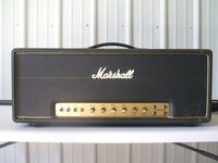
Any photos of your '72?
 
Yeah, always fuse Mains hot. Not neutral. It's a pretty common "must do" mod to vintage amps. I have a '71 Super Lead incoming that will require this as well.

Any photos of your '72?
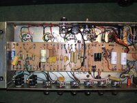
It originally had a Mustard on V1A and a .68uf mustard on V2A but the epoxy coating was cracked and tearing off as whoever at Marshall built this amp used silicone on alot of the components to the board and it had pulled the epoxy off the foil of the cap. You can still see some on the smaller .022uf I left on the board. It also had a weird cylindrical metal cased electrolytic .0022uf coupling cap and most of the rest of the amp had the chicklet coupling caps everywhere else. I installed the .1uf PI caps and the Philips Chicklet .68uf on V1A quite a few years ago and I pulled the ceramic 500pf mixer bright cap because it was really harsh sounding, I replaced it with an NOS mica CDE 560pf cap as I had run out of my Lemco and RS 560pf micas, the CDE sounds just as good. I also found the 5000pf Lemco was contributing to this amps harshness, some say they can leak DC when they age, so I replaced it with an new NOS Mallory 5000pf. THis amp had always been kinda harsh but it smoothed out nicely after the 2019 rebuild and is in line with my 68 NOS Metro build. This amp used to belong to one of my best friends who I was in a band with for a short time in 1990. After he passed tradgicly I inherited the amp in 2007 and keep it going in his memory.

Your 71 from Marshallmel was still using the 1970 reddish boards, which is desirable IMHO:2thumbsup:, are you going to restore it or mod it?
 

Attachments

  • DSCF3103.JPG
    DSCF3103.JPG
    290.9 KB · Views: 35
  • DSCF3030.JPG
    DSCF3030.JPG
    967.6 KB · Views: 35
It originally had a Mustard on V1A and a .68uf mustard on V2A but the epoxy coating was cracked and tearing off as whoever at Marshall built this amp used silicone on alot of the components to the board and it had pulled the epoxy off the foil of the cap. You can still see some on the smaller .022uf I left on the board. It also had a weird cylindrical metal cased electrolytic .0022uf coupling cap and most of the rest of the amp had the chicklet coupling caps everywhere else. I installed the .1uf PI caps and the Philips Chicklet .68uf on V1A quite a few years ago and I pulled the ceramic 500pf mixer bright cap because it was really harsh sounding, I replaced it with an NOS mica CDE 560pf cap as I had run out of my Lemco and RS 560pf micas, the CDE sounds just as good. I also found the 5000pf Lemco was contributing to this amps harshness, some say they can leak DC when they age, so I replaced it with an new NOS Mallory 5000pf. THis amp had always been kinda harsh but it smoothed out nicely after the 2019 rebuild and is in line with my 68 NOS Metro build. This amp used to belong to one of my best friends who I was in a band with for a short time in 1990. After he passed tradgicly I inherited the amp in 2007 and keep it going in his memory.

Your 71 from Marshallmel was still using the 1970 reddish boards, which is desirable IMHO:2thumbsup:, are you going to restore it or mod it?

Not too shabby! I see a few interesting changes in that one. The use of epoxy... you sure that was done at the factory?

I actually prefer the lighter, tan boards! They look cooler to me and easier to clean up since you can see where all the gunk is haha.

As far as the '71 goes, plans haven't been set in stone yet.
I'm going to probably replace the filter caps while I have plenty of room the work and replace the .1uf in the PI back to the original .022uf mustards since I have some ready to go in and re-install a red dogbone 47pf PI fizzy cap. The 31 year old LCR's that i replaced for the previousowner in 1994 are in great shape but since I have brand new ARS filter caps sitting here I may as well replace them now as well as installing a new black bat switch that was broken and replaced with an all metal one years ago..

Yeah I have every reason to believe the silcone RTV/hot glue was from the Marshall factory, this amp also did not have the die makers red die on any solder joints in the amp, not a single one...I can't imagine some tech gooping the amp up as that takes time but ya never know. The RTV or some type of hot glue was on the original Erie V1A, electrolytic , V1B, V2A the old Bias caps, the .022uf coupling caps and I also found V2A was a 1K Iskra instead of an 820, I have some Iskras for it not sure If I want to swap to an 820 or keep it as it was built......dunno.....:unsure::dunno:

Congrats on your incoming 71, that amp has all original iron and sounds really good from the clips posted of it and should be a great base for whatever you decide to do with it.:2thumbsup:

I've seen 1K V2a cathode resistors before. But not super common in my experience. I've not seen epoxy/glue though.
 
I've seen 1K V2a cathode resistors before. But not super common in my experience. I've not seen epoxy/glue though.
Yeah I haven't seen the silicone rtv/hot glue around components in vintage Marshall's either so either this was a one off or some tech got to this amp fairly early in it's life. Thank god the stuff scrapes off the board without too much trouble but the trouble arises with pulling the epixy coating off of the Mustards like it did, luckily I had an inventory of NOS mustards but man .68uf are getting hard to find in 2025.

I keep seeing alot of 1972 amps with that 1K on V2A....I guess 820's were low in inventory in 1972 or one of the builders liked 1K's for that spot.
 
Chiming in to say fuse hot. Blowing the fuse kills the line to the rest of the amp making it "safer" than it was. Note, before the fuse blows the caps will hold charge, so you would need to safely discharge them before service. That JCM schematic you posted shows the hot fused as well. Good luck and be safe.
 
I'm going to probably replace the filter caps while I have plenty of room the work and replace the .1uf in the PI back to the original .022uf mustards since I have some ready to go in and re-install a red dogbone 47pf PI fizzy cap. The 31 year old LCR's that i replaced for the previousowner in 1994 are in great shape but since I have brand new ARS filter caps sitting here I may as well replace them now as well as installing a new black bat switch that was broken and replaced with an all metal one years ago..

Yeah I have every reason to believe the silcone RTV/hot glue was from the Marshall factory, this amp also did not have the die makers red die on any solder joints in the amp, not a single one...I can't imagine some tech gooping the amp up as that takes time but ya never know. The RTV or some type of hot glue was on the original Erie V1A, electrolytic , V1B, V2A the old Bias caps, the .022uf coupling caps and I also found V2A was a 1K Iskra instead of an 820, I have some Iskras for it not sure If I want to swap to an 820 or keep it as it was built......dunno.....:unsure::dunno:

Congrats on your incoming 71, that amp has all original iron and sounds really good from the clips posted of it and should be a great base for whatever you decide to do with it.:2thumbsup:
I had one that didn't have the red dye and people swore that it wasn't original. I don't believe it was ever changed/modified and the guy I bought it from was the original owner. But that was a long time ago.
 
Yeah I haven't seen the silicone rtv/hot glue around components in vintage Marshall's either so either this was a one off or some tech got to this amp fairly early in it's life. Thank god the stuff scrapes off the board without too much trouble but the trouble arises with pulling the epixy coating off of the Mustards like it did, luckily I had an inventory of NOS mustards but man .68uf are getting hard to find in 2025.

I keep seeing alot of 1972 amps with that 1K on V2A....I guess 820's were low in inventory in 1972 or one of the builders liked 1K's for that spot.

Yeah 0.68uF mustards are stupid hard to find. And when you find them, they're like $80 lol.

And yes, it's possible 820R were out of stock at that time, so they used 1K.
 
I had one that didn't have the red dye and people swore that it wasn't original. I don't believe it was ever changed/modified and the guy I bought it from was the original owner. But that was a long time ago.

You still have photos? I do know Marshall built amps without the red dye from time to time. But it's pretty easy to tell what's original and what isn't from looking.
 
I had one that didn't have the red dye and people swore that it wasn't original. I don't believe it was ever changed/modified and the guy I bought it from was the original owner. But that was a long time ago.
The only red rye I have found is on the transformer nuts. I highly doubt every single solder joint had been reflowed in this amp.
:dunno:
 
Back
Top