H
harddriver
Well-known member
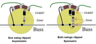
My basic understanding with zeners is the striped end is negative side of the zener. If you orient the negative side facing outward from each other that is assymmetrical clipping. If you orient then positive sides out then that would be symmetrical clipping.I think you might be confused about asymmetrical vs symmetrical clipping. If you have two zeners arranged for diode clipping and they are both 20v, that's symmetrical. If one is 20v and the other is 16v, that's asymmetrical. If you have two 2N5401 or 2N5400 transistors, that's symmetrical. Two MPSA06 are still symmetrical. Mix and match two different transistors and wire them up to clip like zeners, and that's asymmetrical.
The symmetry or asymmetry of a voltage clamping circuit is determined by the positive or negative clipping thresholds. If you clip the signal at +15 volts and -15 volts, that's symmetrical. If you clip the signal at +15 volts and -5 volts, that's asymmetrical.
It has nothing to do with the polarity of the diode or transistor.
Make sense?
I'm always open to hear another viewpoint.