Randall MTS RM50 heater supply problem

BesaMoogie

BesaMoogie

Well-known member
Hi guys, I need some help with a Randall RM50 and how to proceed with the problem.
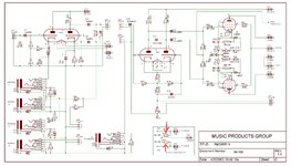
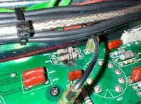
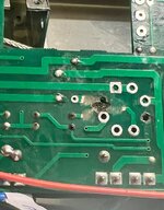
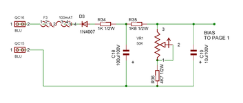
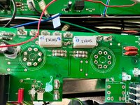
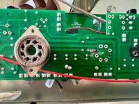
It look likes, the heater supply was "overloaded" causing tow 100R 1W resistors to blow. Have a look on the schematics and pictures I attached. The resistors are located at the bottom right of the schematic.

The amp blow its main fuse. Replacing the fuse just causes to blow it again.

I`m a bit hesistant to just replace the two blwon resistors and power it up again. So what could cause this problem and what is the best way to trouble shoot this?
Is there possibly a short in the PT overlaoding the HT supply?
Would taking out the PT and checking first be the way to go?

So far I checked the Output tubes and they are ok, I don`t have the preamp tubes to check.
The Chassis/Ground connection (see schematic) is ok as well.

Thanks!
 

Attachments

  • ffc1f66e-ceab-4d07-91d9-55beaf01c30a.jpg
    ffc1f66e-ceab-4d07-91d9-55beaf01c30a.jpg
    211.8 KB · Views: 22
  • IMG_9628 2.jpg
    IMG_9628 2.jpg
    1.3 MB · Views: 17
Unplug the green wires from the Board, if it still blows, then the Heater Windings damaged the rest of the Transformer..
 
Typically if the heater winding is compromised I’d toss the whole PT.

I’d also worry about internal ground shorts at those traces and surrounding areas - you will need to ohm out the board to make sure it’s not structurally compromised and that no shorts to ground exist from any supply to ground not just the heater taps.

You’ll need to flex the board slightly to check for hairline cracks. Typically when something that high power goes there’s more to check than just the obvious.
ok, I will remove the whole PCB and make thorough inspection. Probably will remove the whole transformer as well in ths process and check it through
Thanks
 
ok, so I checked the transformer and it`s ok. Took me some time to get the specs for it, but the voltages are all in the right range.

On thing I saw when removing the PCB was another blow under one of the powertube sockets. It happened between the heater and the trace leading to the control grid (see picture). So the problem could possibly not be related to the heater supply in the first place.

I "cleaned" it up and checked the componets upstream of the of the control grid. It looks like the bias circuit was changed at one point in the amp. Some values don`t match the schematic. R35 ist 1.8K in the schematic and was changes to a high wattage 3.3K resistor. C19 was changed from 10uF to 22uF. (see picture).

Could this be my problem?
 

Attachments

  • IMG_9658.jpg
    IMG_9658.jpg
    311.2 KB · Views: 10
  • Bildschirmfoto 2025-04-29 um 15.20.59.png
    Bildschirmfoto 2025-04-29 um 15.20.59.png
    104.6 KB · Views: 10
The heater circuit is different than the bias circuit. Unless there’s an issue with the grounds they shouldn’t have an issue that’s related.

Reduce the 22uf back to 10uf and change the series resistor back to 1.8k. Bias circuits don’t pull any current but their job is to get voltage reference to the grids. Neither of the mods are beneficial to 3charge time.

The false center tap resistors need to have their pads inspected for a good connection to ground. You may have to do some scraping to remove carbon and get to good copper.


That board is toast. Blew the traces and pads for the socket clean off plus you have the damage to the high wattage false center tap resistors. There’s no mechanical leverage for a new socket that won’t allow movement to occur causing compromised solder joints.

I think this board is toast and you’re looking at a new board.

I think what happened was that a tube arced from plate to cathode to heater and that’s what did it in.
 
Last edited:
The heater circuit is different than the bias circuit. Unless there’s an issue with the grounds they shouldn’t have an issue that’s related.

Reduce the 22uf back to 10uf and change the series resistor back to 1.8k. Bias circuits don’t pull any current but their job is to get voltage reference to the grids. Neither of the mods are beneficial to 3charge time.

The false center tap resistors need to have their pads inspected for a good connection to ground. You may have to do some scraping to remove carbon and get to good copper.


That board is toast. Blew the traces and pads for the socket clean off plus you have the damage to the high wattage false center tap resistors. There’s no mechanical leverage for a new socket that won’t allow movement to occur causing compromised solder joints.

I think this board is toast and you’re looking at a new board.

I think what happened was that a tube arced from plate to cathode to heater and that’s what did it in.
Sadly, I don`t see any chance, getting a new PCB for this amp. The amp is not in production anymore and it was more of a niche product when it was. So finding a new PCB is like winning the lottery.

Thinking of mechanical leverage, what you see in this picture is the topside of the PCB. So the socket sits on this side with its solder joints on the opposite site of the board. On the opposite site, all eyelets are still intact and every pin can be soldered. (see pictures) The socket itself then is monted with screws to the chassis, so there is no downward pressure, when installing a tube.

The whole PCB is held in place by multiple tube sockets and jacks.

The amp does not belong to me but to a friend. In the end it`s either using it for spare parts or trying to prolong its lifespan.
 

Attachments

  • IMG_9672.jpg
    IMG_9672.jpg
    1.5 MB · Views: 0
  • IMG_9673.jpg
    IMG_9673.jpg
    1.2 MB · Views: 0
This is a good reason for manufacturers not to board mount high power tube sockets and get bold with trace routing around the pins. They don’t account for fault failure damage mitigation and rely on the sockets for mechanical mounting of the PCB.

I’d tell the guy it’s not safe to repair it. Flying lead style repairs I’ll do on low voltage traces but if anything’s damaged on the high power side it’s not worth the fire hazard risk or safe. I’d chuck it and/or sell it for parts and move on.
 
And to answer your question I do believe the 3.3k combined with the 22uf cap are the reason the tubes arced in the first place. Too long without grid bias and not waiting to flip it out of standby for heaters and bias to stabilize before B+ is given to the plates. Old tubes also don’t help matters.
 
And to answer your question I do believe the 3.3k combined with the 22uf cap are the reason the tubes arced in the first place. Too long without grid bias and not waiting to flip it out of standby for heaters and bias to stabilize before B+ is given to the plates. Old tubes also don’t help matters.
ok, thanks for your help. I will talk to my friend and tell him the situation. Maybe there`s a chance to source a new PCB through one of the MTS modders, but I don`t see a big chance for that.
Cheers
 
Back
Top