Starting a 2204 build

  • Thread starter Thread starter ledvedder
  • Start date Start date
One side of the 50/50 is used in the plexi layout because the other side is one of your 32/32 caps I believe (correct me if I’m wrong)

In your amp that 32/32 is actually for filtering closer to V1 it seems like.

Can you draw a schematic of where it’s at now for us?
 
Ok, I've redone the underboard wiring as it is in this layout.
Screenshot_20220814_214750_Acrobat for Samsung.jpg


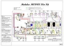
Now, I'll have to sort things out with the power and both 50/50 can caps. I originally wired them as they are in this 800 layout, but I'm assuming I'll need to redo it to align with the Plexi layout above. I still can't wrap my head around why only 1 half of the 50/50 can cap is used in the Plexi layout, yet both halves are used in the 800 layout.
Screenshot_20220814_214739_Acrobat for Samsung.jpg
 

Attachments

  • Screenshot_20220814_214739_Acrobat for Samsung.jpg
    Screenshot_20220814_214739_Acrobat for Samsung.jpg
    453.7 KB · Views: 141
Did you also fix the connections on top of the board? From your photos, those were wired incorrectly as well.
 
Maybe they don't use the other side of that cap in the Plexi kit so it gives the amp a more vintage feel, with less filtering? I dunno. You can certainly use both sides. I would. Take a look a Ceriatone layout for ideas. Your preamp filter cap is only 33+33. I prefer 50+50. So you might want to add that other half of the off-board cap to bump your amp's B+ supply up a bit.
 
Maybe they don't use the other side of that cap in the Plexi kit so it gives the amp a more vintage feel, with less filtering? I dunno. You can certainly use both sides. I would. Take a look a Ceriatone layout for ideas. Your preamp filter cap is only 33+33. I prefer 50+50. So you might want to add that other half of the off-board cap to bump your amp's B+ supply up a bit.
I did look at the Ceriatone layout today. I rewired the caps, choke, etc to their layout. I'm going to try the preamp at 33+33 first. I have an extra 50+50 that I can swap in if I don't like it.
 
I did look at the Ceriatone layout today. I rewired the caps, choke, etc to their layout. I'm going to try the preamp at 33+33 first. I have an extra 50+50 that I can swap in if I don't like it.
I personally hate that vintage squish in a 2203/2204 circuit but since you’re aiming for the plexi vibe you may enjoy the 33/33. You can always try one side of the 50/50, or put both in parallel and you’ve got 100uF you can add in case the 33/33 is way off.
 
I personally hate that vintage squish in a 2203/2204 circuit but since you’re aiming for the plexi vibe you may enjoy the 33/33. You can always try one side of the 50/50, or put both in parallel and you’ve got 100uF you can add in case the 33/33 is way off.
Maybe I'll put the 50/50 that I have in place of the 33/33 for the preamp. I already have my Plexi build with 32/32. I wired the power like this Ceriatone layout, so I'm using both of the 50/50 cans now. 100 mains, 50 screens, and 50 PI.
JCM800_2204Ceriatone (1).jpg
 
I replaced the 32/32 preamp cap with the 50/50. Still have to touch up some of those solder points.
20220823_140718_copy_4000x3000.jpg
 
Where's that blue wire going? Turret on the right?
The blue wire is connected to the turret where the 2 10k resistors meet. There's nothing connected to the middle turret. That's where one of the legs from the old 32/32 cap was.
 
I think I'm ready to fire this baby up for testing 🤞

I just have to decide which tap to run the NFB.
 
You're running 100K NFB? I would start with 8ohm. Then try 4ohm if you want it more raunchy.
 
I'm definitely having a power issue. With no tubes, all heaters measure 6.3v. With all 3 preamp tubes, still 6.3v. With power tubes in, all heaters drop to 5v. So weird!
 
So we need voltages on all pins. Check your grounds. Is this in standby only?
 
So we need voltages on all pins. Check your grounds. Is this in standby only?
All pins of output tube sockets, or output and preamp? With or without tubes installed?

Also, as soon as I power it on with output tubes installed, my light bulb limiter stays dimly lit. It doesn't stay lit with only preamp tubes installed, or no tubes at all.
 
All pins of output tube sockets, or output and preamp? With or without tubes installed?

Also, as soon as I power it on with output tubes installed, my light bulb limiter stays dimly lit. It doesn't stay lit with only preamp tubes installed, or no tubes at all.

No power tubes installed but do install all preamp tubes. Grab a variac. Turn variac to 0V and have the amp out of standby and fully on. Watch your light bulb limiter. Plug in a load. Slowly turn on the variac and monitor B+ and heater voltage. Check for odd smells. DO NOT HAVE YOUR FACE OVER/IN THE AMP ON INITIAL TURN ON.

Post preamp socket voltages on all pins including grounds.

Adjust the bias circuit and make sure the negative voltage changes as expected. Set to the coldest setting (most negative voltage) which sets the tubes in hard class B on initial turn on.

Power off and install power tubes. Repeat variac test. This time monitor heater voltage, B+ voltage, and bias voltage.

Slowly rise and check to make sure the PT and OT stay ice cold. If all turns out well, post all socket voltages out of standby while in hard class B.

As bias is turned more positive, B+ should go down. You can’t bias it until the amp has idled for a good 20 minutes as the tubes have to be at the correct operating temp. Before you can do this we have to track down the heater problem.
 
I had already done the full variac power up with no tubes installed, using the procedure here, https://robrobinette.com/Tube_Amp_Startup.htm.

Here are the voltage readings on both power tube socket pins. Top is without power tubes, bottom is with them. All preamp tubes were installed for both readings.
20220824_001150_copy_2660x3707.jpg
 
Back
Top