Thoughts on my Jose 2204

  • Thread starter Thread starter FourT6and2
  • Start date Start date
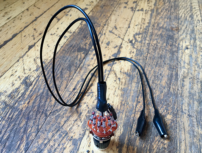
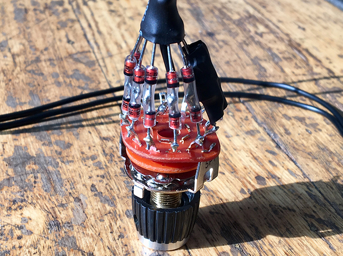
I just made a little decade box of zeners to test out. I'll clip it across the master and go to town!

24v
20v
18v
16v
12v
9.1v
5v transitors
4v transistors

zener_decade_by_haftelm-dckz9vk.jpg


zenerdecade_by_haftelm-dckz9v9.jpg
 
Clean build as usual. My favorite I've tried is 4x MPSA06 connected BE-EB-BE-EB (order probably doesn't matter, that's just how I saw it). MPSA42 are 6v, they are pretty cool too.
 
SpiderWars":nc2kcguy said:
Clean build as usual. My favorite I've tried is 4x MPSA06 connected BE-EB-BE-EB (order probably doesn't matter, that's just how I saw it). MPSA42 are 6v, they are pretty cool too.

So with four MPSA06, you're getting an 8v clamp? Is it even additive like that? The first pair will clamp the signal at 4v. The next pair are seeing a 4v signal, so are they even doing anything? If it is additive, and you're getting an effective 8v, why not just use two 8v zeners?
 
transistor voltage is what is given in the data scheet.

in reality, it will be higher.

my 2n5400 or mpsa06 were all in 10-12v range in reality, i switched between them and 11v zener, almost no difference...
 
FourT6and2":3rfk85yb said:
SpiderWars":3rfk85yb said:
Clean build as usual. My favorite I've tried is 4x MPSA06 connected BE-EB-BE-EB (order probably doesn't matter, that's just how I saw it). MPSA42 are 6v, they are pretty cool too.

So with four MPSA06, you're getting an 8v clamp? Is it even additive like that? The first pair will clamp the signal at 4v. The next pair are seeing a 4v signal, so are they even doing anything? If it is additive, and you're getting an effective 8v, why not just use two 8v zeners?
I've had 2x MPSA06 on one side of a 3-way and 4x on the other and the clipping is less/volume higher on the 4x side. But when compared to regular zeners the voltages didn't correspond. In my King Kong I had 2x MPSA06 + 2x 2N5400 and it wasn't that different in volume/clipping than the 20v zeners on the second Master volume. You could spend alot of time experimenting (I didn't have a decade box) so once I found the combo I liked best I went with it. So that's why I didn't just use zeners instead. I was also experimenting with asymmetrical clipping at the time.
 
FourT6and2":2po4a2he said:
I just made a little decade box of zeners to test out. I'll clip it across the master and go to town!

24v
20v
18v
16v
12v
9.1v
5v transitors
4v transistors

zener_decade_by_haftelm-dckz9vk.jpg


zenerdecade_by_haftelm-dckz9v9.jpg

That looks cool. I bet it would be awesome to incorporate it into the actual build. I wish my CCV had something like this for the solo channel. My only complaint with it is the difference between the mid gain and high gain clipping. The mid gain is a lot less and the amp tends to thin out if I have it set to sound best for high gain or high gain sounds mushy if I have it set for mid gain. I’ve considered changing the mid gain clipping to be closer to the high gain. My only reservation is that what happens in a few years if my ear changes and I’m into lower gain stuff? Hence why I’m pushing you toward that multi switch. :D
 
psychodave":umgeapsj said:
FourT6and2":umgeapsj said:
I just made a little decade box of zeners to test out. I'll clip it across the master and go to town!

24v
20v
18v
16v
12v
9.1v
5v transitors
4v transistors

zener_decade_by_haftelm-dckz9vk.jpg


zenerdecade_by_haftelm-dckz9v9.jpg

That looks cool. I bet it would be awesome to incorporate it into the actual build. I wish my CCV had something like this for the solo channel. My only complaint with it is the difference between the mid gain and high gain clipping. The mid gain is a lot less and the amp tends to thin out if I have it set to sound best for high gain or high gain sounds mushy if I have it set for mid gain. I’ve considered changing the mid gain clipping to be closer to the high gain. My only reservation is that what happens in a few years if my ear changes and I’m into lower gain stuff? Hence why I’m pushing you toward that multi switch. :D

You can always try to install some sort of harness or clamp type of connection where you can just plug and play zeners without soldering? Or hey, replacing a few diodes once every couple of years to get a new flavor of gain ain’t the biggest thing haha.

Or just build one of these switches! Took me about an hour
 
FourT6and2":1bbmzt5e said:
psychodave":1bbmzt5e said:
FourT6and2":1bbmzt5e said:
I just made a little decade box of zeners to test out. I'll clip it across the master and go to town!

24v
20v
18v
16v
12v
9.1v
5v transitors
4v transistors

zener_decade_by_haftelm-dckz9vk.jpg


zenerdecade_by_haftelm-dckz9v9.jpg

That looks cool. I bet it would be awesome to incorporate it into the actual build. I wish my CCV had something like this for the solo channel. My only complaint with it is the difference between the mid gain and high gain clipping. The mid gain is a lot less and the amp tends to thin out if I have it set to sound best for high gain or high gain sounds mushy if I have it set for mid gain. I’ve considered changing the mid gain clipping to be closer to the high gain. My only reservation is that what happens in a few years if my ear changes and I’m into lower gain stuff? Hence why I’m pushing you toward that multi switch. :D

You can always try to install some sort of harness or clamp type of connection where you can just plug and play zeners without soldering? Or hey, replacing a few diodes once every couple of years to get a new flavor of gain ain’t the biggest thing haha.

Or just build one of these switches! Took me about an hour

I considered that...it’s a bitch to lift the board and get to them.
 
Nice, I've built these selection switches before for fuzz/distortion pedals. However I always only found one or two selections I liked.

This will definatally work great for a decade box when your building an amp, and trying to find the value that sounds best.

One thing, when you build decade boxes, make the leads short as possible.
 
FourT6and2":1empxnhg said:
V2a":1empxnhg said:
FourT6and2":1empxnhg said:
Ok, thanks! So that said... why would someone build a NEW amp (not a mod of an existing amp) with a 100K bypassed with a 330pF cap and then a 220K resister in series, to the socket? Why not just use a single 320K or 330K resister?

I can think of two reasons (one good, one not so good):
1. Copy the popular Friedman setup
2. Because the partial bypass results in less attenuation in the stop band. In the case of a partial anode bypass, you'll attenuate but not completely lose those high frequencies.


So what was the reason MF used the Friedman setup in that expensive new amp you just purchased? It has to be either 1 or 2.

Interesting. The amp you're referring to is very bright. So personally, I want more attenuation of some of the highs. My thoughts are to try one or more of the following if I ever build something similar.

1. Up the PI fizz cap from 47pF to 100pF
2. Go with a 330K resistor bypassed for V1a plate
3. 0.001uF cap off V1b grid to ground
4. 0.001uF cap in series from V1a coupling cap to ground

On a related note, yes the expensive new amp is a bit... surprising... since it's a 2204 with some diodes :lol: :LOL: and it seems I've already built a bunch just like it :doh:
It's not a bad sounding amp. It's just too bright for my taste. There are a small number of useful tidbits I might implement into my next build. I just prefer a darker voicing since I don't play 8-strings tuned down 5 steps.


In my opinion (based on limited experimentation), it makes a difference once the excursion plus recovery starts to last more than 10 ms. A change of a few milliseconds isn't going to be noticeable (I don't think).

Why use 150k grid leaks and 10k stoppers? There are many reasons, including not-so-good reasons (1. people are experimenting without having a decent understanding; 2. people are holding on to vintage values or other legacy values).

Good reasons include the following factors:
- all tubes have limits to the resistance in the grid circuit. The limits depend on whether the tube has fixed bias or cathode/self bias. The 6V6 has a 100k ohm limit in fixed bias, so that the total resistance between the PI coupling cap and each output tube grid should be less than 100k! That includes the grid leaks (normally 220k), the grid stopper (1-10k), and any other series resistance you put in place to limit the signal (see the Aiken link that I posted earlier).
- someone might lower the grid leak to be within limits
- someone might increase the grid stopper to reduce oscillations, etc. The stopper can be much higher than typical before the audio frequencies are affected.

Thank you

I just realized the amp you’re referring to is the new Fortin Meshugga. I know it was a Jose amp based on Reza bringing his first one to Friedman and telling us it was a Jose.

Kinda makes you wonder why all of those videos sound big and massive with tons of bottom end (we know it doesn’t have a depth circuit). Must be great production since you mention it is bright.
 
psychodave":1b172wgu said:
FourT6and2":1b172wgu said:
V2a":1b172wgu said:
FourT6and2":1b172wgu said:
Ok, thanks! So that said... why would someone build a NEW amp (not a mod of an existing amp) with a 100K bypassed with a 330pF cap and then a 220K resister in series, to the socket? Why not just use a single 320K or 330K resister?

I can think of two reasons (one good, one not so good):
1. Copy the popular Friedman setup
2. Because the partial bypass results in less attenuation in the stop band. In the case of a partial anode bypass, you'll attenuate but not completely lose those high frequencies.


So what was the reason MF used the Friedman setup in that expensive new amp you just purchased? It has to be either 1 or 2.

Interesting. The amp you're referring to is very bright. So personally, I want more attenuation of some of the highs. My thoughts are to try one or more of the following if I ever build something similar.

1. Up the PI fizz cap from 47pF to 100pF
2. Go with a 330K resistor bypassed for V1a plate
3. 0.001uF cap off V1b grid to ground
4. 0.001uF cap in series from V1a coupling cap to ground

On a related note, yes the expensive new amp is a bit... surprising... since it's a 2204 with some diodes :lol: :LOL: and it seems I've already built a bunch just like it :doh:
It's not a bad sounding amp. It's just too bright for my taste. There are a small number of useful tidbits I might implement into my next build. I just prefer a darker voicing since I don't play 8-strings tuned down 5 steps.


In my opinion (based on limited experimentation), it makes a difference once the excursion plus recovery starts to last more than 10 ms. A change of a few milliseconds isn't going to be noticeable (I don't think).

Why use 150k grid leaks and 10k stoppers? There are many reasons, including not-so-good reasons (1. people are experimenting without having a decent understanding; 2. people are holding on to vintage values or other legacy values).

Good reasons include the following factors:
- all tubes have limits to the resistance in the grid circuit. The limits depend on whether the tube has fixed bias or cathode/self bias. The 6V6 has a 100k ohm limit in fixed bias, so that the total resistance between the PI coupling cap and each output tube grid should be less than 100k! That includes the grid leaks (normally 220k), the grid stopper (1-10k), and any other series resistance you put in place to limit the signal (see the Aiken link that I posted earlier).
- someone might lower the grid leak to be within limits
- someone might increase the grid stopper to reduce oscillations, etc. The stopper can be much higher than typical before the audio frequencies are affected.

Thank you

I just realized the amp you’re referring to is the new Fortin Meshugga. I know it was a Jose amp based on Reza bringing his first one to Friedman and telling us it was a Jose.

Kinda makes you wonder why all of those videos sound big and massive with tons of bottom end (we know it doesn’t have a depth circuit). Must be great production since you mention it is bright.

I doubt it's "production." But yeah the thing is uber bright. Then again, aren't stock JCM800s also super bright?
 
CrazyNutz":2yr3pl2z said:
FourT6and2":2yr3pl2z said:
Any more info about the dropper? I know most amps have a 10K there. The last 3 I built, I didn't use it (admittedly, I just did that because I was starting with a Ceriatone layout and they don't use a dropper. The amps sound pretty good to me. I figure I want to keep the preamp voltages higher for a tighter feel/sound. Is there any reason why that's a bad idea? Without the dropper, I'm JUST hitting the voltages I want. With another dropper there, I think the voltages would be too low. I've been going back and forth on it. Maybe I'll just try it this time.


Those interstage droppers play a few important roles:
1) They decouple the amplifier stages. Without it your Cath follower, and PI Stages are coupled, and can interact
2) Provide a local energy supply for sudden current demands. Without it, your Cath follower could be robbing power from the PI, and vice versa.
3) Further smooth, and reject ripple.

If you wan't higher preamp voltage it's customary to adjust the first dropper where the voltage enter the preamp.

Also if you like the higher voltage, you may want to lower the plate resistor on V1A from 390k to 330k

you can read more here: http://www.valvewizard.co.uk/smoothing.html

Solid advice. Thanks!
 
Haven't built the amp in the schematic yet. But I did play around with my stock Chupacabra today.

I prefer a 36K slope over the stock 47K (added a variable slope/mid shift control) and I lowered V1a plate load to 320K, from 475K, to raise the voltage a bit on that stage (it's now around 118v). Could probably still go higher. Might try a 220K and see what happens. Those two changes really turned the amp into a monster. It's been my favorite amp for years. But the variable slope + higher voltage on the first stage were a great mod.

I also hooked that zener decade box up to it to test. Works great. I used a make-before-break switch so there's not jump in volume. 24v, 20v, 18v, and 16v zeners all sound great depending on what mood you're in. I think 18v is a good middle ground. But I like the 16v and 20v too. The MPSA06 are interesting too for more modern levels of gain. They have a sort of vocal quality which is cool.

I might have to throw 4-5 combos into the amp on a switch. It's hard to choose.
 
You can increase the resistive load when you lower the plate resistor. With a 220k plate R, try replacing each 68k resistor with 330k-470k
 
V2a":uf5eap8x said:
You can increase the resistive load when you lower the plate resistor. With a 220k plate R, try replacing each 68k resistor with 330k-470k

Sorry, two different amps here. I'm still playing around with the schematic in the OP before I actually build that amp. Still have a few things I need to work out. My last post was about a stock Ceriatone Chupacabra, which is basically the same circuit for all intents and purposes. In that amp, it has an 82K to ground off Gain 1 wiper and a 150K on V1b grid instead of two 68Ks. Those are the resistors you're talking about, though, right?
 
Yes, you are correct. I am touring wineries and not very helpful. But in general you can increase the load when you lower the plate resistor. Try increasing the 82k to 330k-470k.
 
V2a":dc7kjtdb said:
Yes, you are correct. I am touring wineries and not very helpful. But in general you can increase the load when you lower the plate resistor. Try increasing the 82k to 330k-470k.

Would you suggest lowering the 150K V1b grid as well? Do you want to keep a certain ratio between the two?

As far as I can tell, the higher the value of that resistor from wiper to ground, the more gain it shunts? Engaging that resistor (on a switch) seems to cut saturation and stiffen up the response of the amp a bit. 82K is almost too much. Wouldn't 330K-470K kill all the gain of the stage?
 
FourT6and2":2002bh6v said:
I prefer a 36K slope over the stock 47K (added a variable slope/mid shift control) and I lowered V1a plate load to 320K, from 475K, to raise the voltage a bit on that stage (it's now around 118v).


Yup, never played a chupa, but everytime I've looked at the schematic I thought to myself this is exactly what I would change.
Around 330k is in the sweetspot for v1a, and 33k to 39k for slope for these hot rodded jose style marshall's
 
FourT6and2":zyf3vyk6 said:
V2a":zyf3vyk6 said:
Yes, you are correct. I am touring wineries and not very helpful. But in general you can increase the load when you lower the plate resistor. Try increasing the 82k to 330k-470k.

Would you suggest lowering the 150K V1b grid as well? Do you want to keep a certain ratio between the two?

As far as I can tell, the higher the value of that resistor from wiper to ground, the more gain it shunts? Engaging that resistor (on a switch) seems to cut saturation and stiffen up the response of the amp a bit. 82K is almost too much. Wouldn't 330K-470K kill all the gain of the stage?

the 150k grid stop acts in conjunction with the tube's internal capacitance to roll of some high end; so keep it as is if you like the tone.

The 82k is in parallel with the shunt portion of the gain 1 pot (1MA). So say you have gain 1 set at 50% resistance (at about 3:00 on the dial). 500k in parallel with 82k is 70k, which is darn close to the 68k found in other Jose-type amps.

Two things to think about:
1. Voltage divider: V-out = V-in * (R2 / R1 + R2), where R1 is the series resistance and R2 is the shunt resistance to ground. So the lower the value of R2 in relation to R1, the more gain is shunted to ground (lost). If you replace 82k with a higher-value R, then you'll lose less signal (keeping in mind that 82k is in parallel with the gain 1 pot).

2. the total value of R1 + R2 is effectively in parallel with the plate resistor as far as the preceding tube is concerned. So the lower the total value of R1+R2 (and of the plate resistor), the lower the gain you'll get from the preceding gain stage (because the "load" determines the AC load line; see Blencowe preamp book). If all you do is lower the plate resistor from 470k to 100k, then you will loose gain. But if you also increase the 82k resistor (which is in parallel with gain1 and the plate R) you can get some of that gain back.

The LOWER that (parallel) resistance is, the more gain it shunts (less resistance to ground means more of the signal goes to ground).
 
V2a":2rt94w9l said:
FourT6and2":2rt94w9l said:
V2a":2rt94w9l said:
Yes, you are correct. I am touring wineries and not very helpful. But in general you can increase the load when you lower the plate resistor. Try increasing the 82k to 330k-470k.

Would you suggest lowering the 150K V1b grid as well? Do you want to keep a certain ratio between the two?

As far as I can tell, the higher the value of that resistor from wiper to ground, the more gain it shunts? Engaging that resistor (on a switch) seems to cut saturation and stiffen up the response of the amp a bit. 82K is almost too much. Wouldn't 330K-470K kill all the gain of the stage?

the 150k grid stop acts in conjunction with the tube's internal capacitance to roll of some high end; so keep it as is if you like the tone.

The 82k is in parallel with the shunt portion of the gain 1 pot (1MA). So say you have gain 1 set at 50% resistance (at about 3:00 on the dial). 500k in parallel with 82k is 70k, which is darn close to the 68k found in other Jose-type amps.

Two things to think about:
1. Voltage divider: V-out = V-in * (R2 / R1 + R2), where R1 is the series resistance and R2 is the shunt resistance to ground. So the lower the value of R2 in relation to R1, the more gain is shunted to ground (lost). If you replace 82k with a higher-value R, then you'll lose less signal (keeping in mind that 82k is in parallel with the gain 1 pot).

2. the total value of R1 + R2 is effectively in parallel with the plate resistor as far as the preceding tube is concerned. So the lower the total value of R1+R2 (and of the plate resistor), the lower the gain you'll get from the preceding gain stage (because the "load" determines the AC load line; see Blencowe preamp book). If all you do is lower the plate resistor from 470k to 100k, then you will loose gain. But if you also increase the 82k resistor (which is in parallel with gain1 and the plate R) you can get some of that gain back.

The LOWER that (parallel) resistance is, the more gain it shunts (less resistance to ground means more of the signal goes to ground).

Gold. Thanks.

And duh! Resistors RESIST lol. I'm a dummy sometimes. Makes sense now. If that resistor were 0 ohms, then 100% of the signal would shunt to ground. So yeah, higher values preserve more of the signal = more gain. I don't think this amp needs more gain. It's got plenty as is. But I will definitely try a few different values there to see how it sounds.
 
Back
Top