You are using an out of date browser. It may not display this or other websites correctly.
You should upgrade or use an alternative browser.
You should upgrade or use an alternative browser.
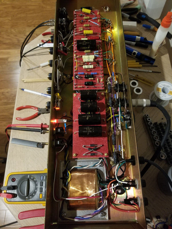
Starting a 2204 build
- Thread starter ledvedder
- Start date
glpg80
Well-known member
Looking really good.
Be sure to minimize how many tiny component leads are leftover after soldering and to trim them as flush with the solder as possible. They can act like little antennas that pickup noise when the chassis is powered on and upside down, but when installed in the headshell, don’t pose as much of a problem due only to the existence of the aluminum shield on the headshell.
Any spots of solder that are sunken in or flat could likely use more solder. You’re looking for rounded shiny solder joints. Sunken in joints can hide air pockets below them that haven’t yet escaped. Never touch an already soldered joint with a hot iron tip without adding flux or more solder.
glpg80
Well-known member
Also maybe I’m missing it but whatever you’re using as chassis ground off of the IEC plug needs to have its own ground AND a lock washer on it. In my amp I do share the ground with one cap but it still is clearly identifiable and has a lock washer. Don’t skip this step - it could kill someone if it comes loose in shipping or by accident moving it around.
ledvedder
Well-known member
Thanks! Yep, I'll go over each joint again when I'm finished to smooth out any that aren't shiny.Looking really good.
Be sure to minimize how many tiny component leads are leftover after soldering and to trim them as flush with the solder as possible. They can act like little antennas that pickup noise when the chassis is powered on and upside down, but when installed in the headshell, don’t pose as much of a problem due only to the existence of the aluminum shield on the headshell.
Any spots of solder that are sunken in or flat could likely use more solder. You’re looking for rounded shiny solder joints. Sunken in joints can hide air pockets below them that haven’t yet escaped. Never touch an already soldered joint with a hot iron tip without adding flux or more solder.
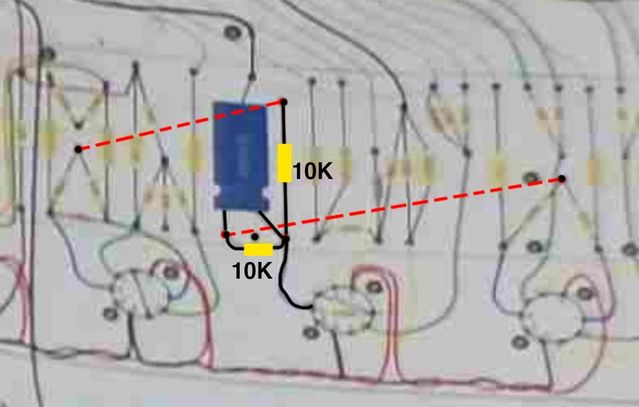
For some reason, I feel like something isn't right in this spot where the dual 32/32 filter cap is.
ledvedder
Well-known member
It's down here.Also maybe I’m missing it but whatever you’re using as chassis ground off of the IEC plug needs to have its own ground AND a lock washer on it. In my amp I do share the ground with one cap but it still is clearly identifiable and has a lock washer. Don’t skip this step - it could kill someone if it comes loose in shipping or by accident moving it around.
glpg80
Well-known member
What would be wrong? I see 32uF to ground, then a series dropping resistor, Are you talking about what’s tapped off of it from those spots? It is tight in there but I can’t see for sure what’s going onThanks! Yep, I'll go over each joint again when I'm finished to smooth out any that aren't shiny.
For some reason, I feel like something isn't right in this spot where the dual 32/32 filter cap is. View attachment 132262
I would have probably zip-tied the cap to the board for extra measure. I like some mechanical restraint for large components like that myself but that’s just my OCD
Last edited:
ledvedder
Well-known member
Should I move the B+ from the right lug of the cap to the left lug (red arrow)? And should I move the right lug of the cap to the same turret where the 2 10k resistors are (blue arrow)?What would be wrong? I see 32uF to ground, then a series dropping resistor, Are you talking about what’s tapped off of it from those spots? It is tight in there but I can’t see for sure what’s going on
I would have probably zip-tied the cap to the board for extra measure. I like some mechanical restraint for large components like that myself but that’s just my OCD
glpg80
Well-known member
Going upstream connectivity wise you should have Phase inverter plate resistors both tapping off of one side of the 32uF, then you have the 10K across each of the 32uF, then the other side of the 32uF should go to your choke and also have continuity to each of your screen grid resistors.


Last edited:
glpg80
Well-known member
As far as convention as to which side of the 32uF B+ is fed to first, it doesn’t matter. What matters is that the choke and both of the phase inverter 100k and 82k plate resistors need a 10K series dropping resistor (in front of the black 32/32) between them electrically and that 32uF is on each side of that same 10K resistor.
So it should go
choke -> (one side 32uF) -> 10k -> (other side 32uF) *** -> 10k
*** is where 82k and 100k phase inverter plate resistors would also connect.
So it should go
choke -> (one side 32uF) -> 10k -> (other side 32uF) *** -> 10k
*** is where 82k and 100k phase inverter plate resistors would also connect.
Last edited:
ledvedder
Well-known member
Thanks for the detailed explanation! I'll have to confirm this on my build.As far as convention as to which side of the 32uF B+ is fed to first, it doesn’t matter. What matters is that the choke and both of the phase inverter 100k and 82k plate resistors need a 10K series dropping resistor (in front of the black 32/32) between them electrically and that 32uF is on each side of that same 10K resistor.
So it should go
choke -> (one side 32uF) -> 10k -> (other side 32uF) *** -> 10k
*** is where 82k and 100k phase inverter plate resistors would also connect.
FourT6and2
Well-known member
Yeah I noticed that earlier with the dual can and 10Ks. Looked odd to me, but I can't see what you have going on there or under the board.
Should go:
PI B+ node –> 10K –> one side of cap. Then that junction goes to tube and you have another 10K from that junction to the other side of the cap. Then that junction goes to V1 plates.
Should go:
PI B+ node –> 10K –> one side of cap. Then that junction goes to tube and you have another 10K from that junction to the other side of the cap. Then that junction goes to V1 plates.
ledvedder
Well-known member
Yeah, I've been trying to figure out what's going on. I'm kinda lost at this point lolYeah I noticed that earlier with the dual can and 10Ks. Looked odd to me, but I can't see what you have going on there or under the board.
Should go:
PI B+ node –> 10K –> one side of cap. Then that junction goes to tube and you have another 10K from that junction to the other side of the cap. Then that junction goes to V1 plates.
FourT6and2
Well-known member
ledvedder
Well-known member
Since I'm using the Modulus smallbox parts, is this the power layout that I should follow? I can't understand why only one side of the 50/50 can cap is used.
Both sides are used in their 800 layout, but the power is also run differently.
SpiderWars
Well-known member
The old Marshall boards had two resistors in series where you have that one 10k/3W between the NFB and bias. Or sometimes they would use one resistor and one jumper. When I built my Superbass I wired it such that the 10k between the PI node and V2 node was there. Then I only needed the 10k between the two lugs of the preamp filter cap. I never liked that other 10k over there in the middle. It seems its always a compromise getting everything to fit.
See the first resistor is 18k and the second one is 10k. Then there is just a 10k/2W on that board-mounted filter cap.
See the first resistor is 18k and the second one is 10k. Then there is just a 10k/2W on that board-mounted filter cap.