JCM800 2204 Cameron HG Jose build thread

  • Thread starter Thread starter harddriver
  • Start date Start date
H

harddriver

Well-known member
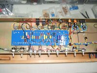
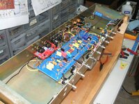
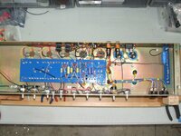
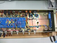
This amp build was on the back burner for quite a few years, collecting specific high end parts and then finding the time and motivation. I finally got the project into the final stretch. I started populating the board today, every component tested to make sure everything was perfectly in spec and just taking my time not rushing anything. I hope to get things finished up this week if my schedule cooperates. Donor amp is a 1984 JCM800 2204 with all original transformers with a B+ of 450-467DCV, I can't remember what it was when I tested it before breaking the amp down.

I got the specs from schematics floating around the internet years ago and then going over pics from actual Cameron HG Jose amps chassis pics from the internet and verifying values and such. The info is out there if you dig. I want to thank all those who helped along the way, you all know who you are and it is very much appreciated.:2thumbsup:

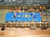
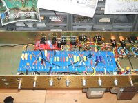
I have added some features that I like, two switchable gain selections, solo control, Depth mod, adjustable NFB control and Elevated heaters to keep the noise floor as low as possible without DC heaters and a Larry grounding scheme. Everything is new, jacks and pots, filter caps, screen grid resistors and I replaced any questionable original wires but original main wire harnesses were like new. The plan is for the amp to be able to use either EL34's or 6550's/KT88's with a 50K bias pot, we'll see how much range that gives me. I'm using Dale and Vishay metal film resistors and Carbon film in certain specific spots, The Dales were used in Soldano SLO's. Pics aren't great but gives you an idea....I'll update pic as things go along. Enjoy the amp porn.:LOL:
 

Attachments

  • DSCF3204.JPG
    DSCF3204.JPG
    898 KB · Views: 101
  • DSCF3206.JPG
    DSCF3206.JPG
    862 KB · Views: 75
Last edited:
I really like vishay dale resistors. I also like vishay beyschlags but I find them a bit noisy even for metal films so I limit their usage. They aren’t carbon comp noisy but still noticeable.

Last thing I’m doing is going to full DC heaters. Have the dedicated supply mounted. I have a bit of 60Hz hum I believe is due to the heaters so elevating them is no longer an option as that would only fix heater to cathode voltage limitations.

Looking forward to your build updates :rock:
 
I remember seeing a lot of orange drop caps in mine
The certain amp I am replicating used the generic 630V polyester coupling caps in the tonestack and second gain stages, the rest of the map was stock Marshall chicklet coupling caps which could be polyester or polycarbonate. I chose to use the IC MPW polypropylene coupling caps for the Phase Inverter but they very similar to Orange Drops. I've used those in an entire HG build before and the caps work very well and sound great.

I am going to get the amp up and running first then install the metro effects loop after seeing where the B+ settles out. I seem to remember this amp being about 455DCV for a B+ when I checked it before the teardown but these years JCM800's are known for as much as 468-470DCV for a 50 watter.
 
I found a little time yesterday and today and made some progress. This is the tedious work, routing the shielded cable making sure they have the perfect lengths with some relief and making sure the effects loop will still fit when it's time for that to go in. This is also the most important section of the amp so I need to make certain the wire dress is as close to perfect and I can make it. I may have to drill the turret board to tie off that shielded cable away from the plate resistors we'll see.

These turrets I got from Watts tube audio( Now Closed) are soldering up great, they take heat quickly and I don't have to stay on the joint's long at all to get nice solder joints. Here a couple of pics of the progress.
 

Attachments

  • DSCF3207.JPG
    DSCF3207.JPG
    947 KB · Views: 43
  • DSCF3208.JPG
    DSCF3208.JPG
    936 KB · Views: 43
Last edited:
I found a little time yesterday and today and made some progress. This is the tedious work, routing the shielded cable making sure they have the perfect lengths with some relief and making sure the effects loop will still fit when it's time for that to go in. This is also the most important section of the amp so I need to make certain the wire dress is as close to perfect and I can make it.

These turrets I got from Watts tube audio( Now Closed) are soldering up great, they take heat quickly and I don't have to stay on the joint's long at all to get nice solder joints. Here a couple of pics of the progress.
That looks like a clean work to me 👍🏻
 
Made some more progress yesterday. I decided to order an NOS part so initial fire up will be delayed some, hopefully I get the part Saturday. I'm hoping to have most everything wired up by this weekend. I'm just test fitting the Metro loop, it will come back out once all the shielded wire is ran.
 

Attachments

  • DSCF3209.JPG
    DSCF3209.JPG
    971.1 KB · Views: 33
  • DSCF3210.JPG
    DSCF3210.JPG
    956.9 KB · Views: 31
Have you experimented with different clamping voltage values?
Yes I have.:yes::2thumbsup: I tend to like 20V zeners oriented asymmetrical clipping, that's what I run in my two other Jose master volume setups but none of them are as gainy as this build.

I have gone down as far as 10 and 6V and felt they were way too saturated. I liked 16V also oriented asymmetrically when you and Redplated were shooting out zeners a while ago so I have 16V ones sitting here as well as a bunch of other values from 20V down to 5V in two volts increments.

I have a three way switch in this amp on/off/on, one will be 20V/20V for sure and I'm going to experiment back down to 5V and see what my ears like now in this amp.

I was digging through my old parts bin and it looks like I tried two generic 2N-5400 transistor(Jose clippers) with one leg cut using the transistor as diodes in the past and I didn't like it then but I didn't use heat sinks when I soldered that one together and may have damaged them with heat.
 
Last edited:
Yes I have.:yes::2thumbsup: I tend to like 20V zeners oriented asymmetrical clipping, that's what I run in my two other Jose master volume setups but none of them are as gainy as this build.

I have gone down as far as 10 and 6V and felt they were way too saturated. I liked 16V also oriented asymmetrically when you and Redplated were shooting out zeners a while ago so I have 16V ones sitting here as well as a bunch of other values from 20V down to 5V in two volts increments.

I have a three way switch in this amp on/off/on, one will be 20V/20V for sure and I'm going to experiment back down to 5V and see what my ears like now in this amp.

I was digging through my old parts bin and it looks like I tried two generic 2N-5400 transistor(Jose clippers) with one leg cut using the transistor as diodes in the past and I didn't like it then but I didn't use heat sinks when I soldered that one together and may have damaged them with heat.

Try 2N5401 or MPSA06 ;)
 
Try 2N5401 or MPSA06 ;)
Isn't the MPSA06 the one Friedman uses for the SAT switch in the BE100? I think I tried that one as well, I'll have to dig through my diode bins again and see if I have an MPSA06.....

Does the 2N5401 have some attributes the 2N5400 doesn't? Does it clip differently? Do these transistors clip in the 3-5V range, I thought someone said that somewhere. That with the 2N5400 with the collector clipped and the emitter connected together with the base legs as the connection points and I think with the that configuration that would be symmetrical slipping with a 2N5401/5400.


With the same configuration the MPSA06 is asymmetrical clipping I think??????

Thanks for the suggestions!:2thumbsup:
 

Attachments

  • 2N5400-Pinout.jpg
    2N5400-Pinout.jpg
    36.3 KB · Views: 11
  • MPSA06-Pinout.jpg
    MPSA06-Pinout.jpg
    36.7 KB · Views: 12
Last edited:
Looks killer! Why no grid stoppers on the power tube grids?
They are there, they are the stock Phier 5.6K resistors on pin 5 if we are talking about the same thing....
 
Last edited:
Isn't the MPSA06 the one Friedman uses for the SAT switch in the BE100? I think I tried that one as well, I'll have to dig through my diode bins again and see if I have an MPSA06.....

Does the 2N5401 have some attributes the 2N5400 doesn't? Does it clip differently? Do these transistors clip in the 3-5V range, I thought someone said that somewhere. That with the 2N5400 with the collector clipped and the emitter connected together with the base legs as the connection points and I think with the that configuration that would be symmetrical slipping with a 2N5401/5400.


With the same configuration the MPSA06 is asymmetrical clipping I think??????

Thanks for the suggestions!:2thumbsup:

There is some ambiguity in the DIY community about the actual clamping voltage of transistors when wired up as zeners. The base-to-emitter breakdown voltage you find on data sheets for transistors is most likely not the same as the clamping voltage you get when wiring them up for diode clipping. This is because they were never designed to be used this way. So manufacturers wouldn't really put that info into spec sheets. Also, I do think that it's possible the same model number transistor from different manufacturers might actually clip at different voltage thresholds when used as zeners. I've not done a direct A/B comparison and measured the clamping voltage of them.

But yes, I do think there's a difference in sound between 2N5401 and 2N5400. At least the ones I've tested.
I'll pick some up I may as well try a bunch of them out to see which ones I like best. :yes::thumbsup:Do you have a brand of 2N5401 that you like?

I think the MPSA06 in this configuration is asymmetrical clipping since it is an NPN transistor with the base leg being the negative side of the polarity. The 2N5400/01 series is a PNP transistor which would be symmetrical because the polarity opposite to the NPN?????

Do I have that correct?
 

Attachments

  • 20v zener MPSA06 clipper.JPG
    20v zener MPSA06 clipper.JPG
    50.6 KB · Views: 20
  • identity-npn-and-pnp-transistors-1024x727.png
    identity-npn-and-pnp-transistors-1024x727.png
    118.8 KB · Views: 20
I'll pick some up I may as well try a bunch of them out to see which ones I like best. :yes::thumbsup:Do you have a brand of 2N5401 that you like?

I think the MPSA06 in this configuration is asymmetrical clipping since it is an NPN transistor with the base leg being the negative side of the polarity. The 2N5400/01 series is a PNP transistor which would be symmetrical because the polarity opposite to the NPN?????

Do I have that correct?

I think you might be confused about asymmetrical vs symmetrical clipping. If you have two zeners arranged for diode clipping and they are both 20v, that's symmetrical. If one is 20v and the other is 16v, that's asymmetrical. If you have two 2N5401 or 2N5400 transistors, that's symmetrical. Two MPSA06 are still symmetrical. Mix and match two different transistors and wire them up to clip like zeners, and that's asymmetrical.

The symmetry or asymmetry of a voltage clamping circuit is determined by the positive or negative clipping thresholds. If you clip the signal at +15 volts and -15 volts, that's symmetrical. If you clip the signal at +15 volts and -5 volts, that's asymmetrical.

It has nothing to do with the polarity of the diode or transistor.

Make sense?
 
I'll need to look at what transistors I have to see if I the bags are labeled for brand/part number and get back to you
 
Back
Top