Metro JTM45 kit is here! Build Progress thread..

  • Thread starter Thread starter cyndicate
  • Start date Start date
Lp Freak":11rvngxu said:
cyndicate":11rvngxu said:
Digital Jams":11rvngxu said:
Looks great, I always want to do one of these but I know it would take forever to complete.

Thanks! It's actually not that bad once you get it going, I have about 4-5 hours in it now, I think i've read that the build will probably take about 10-15 hours total
I've built four of them now and pretty much got it down pat. The last one I started on Friday after work and was playing it Sunday evening. Now that's definately snortin' a lot a solder fumes. :rock:

Nice! I figured I would take my sweet time since it's my first build, but a part of me wants to just take a day off work and finish it :lol: :LOL:
 
Nah, it's best to take your time and triple check your previous session especially solder connections. It only takes one mistake and the amp won't work right. I've gotten the whole amp wired up right before but had one bad connection and the amp sounded like shit. Then you gotta go back and try to figure out what went wrong. Not fun. :no: Damn, now I'm getting the itch to build another. :doh:
 
Do you think the 18 vs 22 gauge wire is a big difference? Looks like I used 22 vs 18 on the speaker output jacks as well :(

Another quick question, the solder I used in the initial stages was 63/37 solder that I bought from Weber, then I tried the 60/40 solder that was included with the kit, I noticed the 60/40 is much more shiny looking when cooled down and the 63/37 is more dull which is kind of hard for me to tell if its a bad solder joint or not, is there a reason for this?

I just have such a big spindle of the 63/37 that it feels like a waste if I am not using it. Just making sure its fine that it doesn't look as "shiny" as the 60/40.
 
I'd definately go with the 18ga buss wire. This is all your grounding and you don't want to end up with a noisy amp. It's alot easier to change it now then later.

Go with the 60/40. A shiny solder joint is good. A dull solder joint usually means a cold or not solid solder joint. The better job you do soldering, the quieter the amp will operate.
 
Lp Freak":2n5pn19f said:
I'd definately go with the 18ga buss wire. This is all your grounding and you don't want to end up with a noisy amp. It's alot easier to change it now then later.

Go with the 60/40. A shiny solder joint is good. A dull solder joint usually means a cold or not solid solder joint. The better job you do soldering, the quieter the amp will operate.

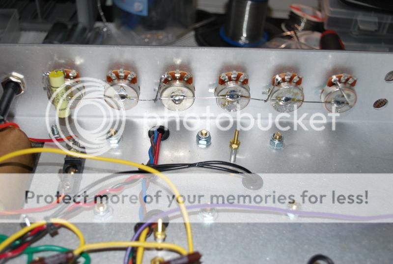
Cool thanks, should be a easy fix for me, it was easier than I thought to solder the bus wire, I just used electrical tape between each pot to hold up the buss wire, then just soldered the center, took longer to file out the holes for each pot to fit correctly :lol: :LOL:
 
Made some more progress during the week!

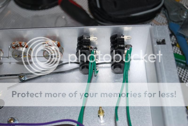
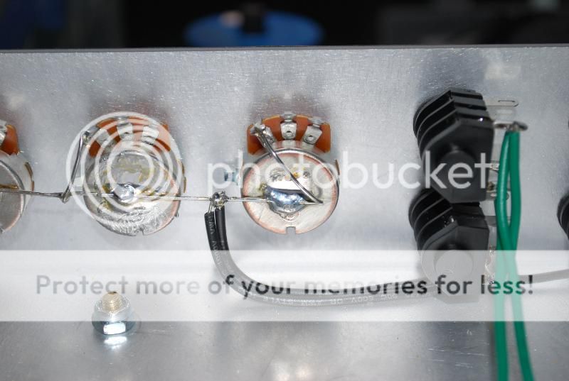
Had to fix my prior mistake of using the wrong bus wire on the ground bus for the pots and the speaker jacks, reinstalled the new wire, I know I should have straightened it but I didn't really bother. Pretty late so I will try to add captions/comments and stuff to this this whole thread later for issues I came across so this can help out whoever else decides to build the kit.

DSC_0030-2.jpg


DSC_0034-1.jpg


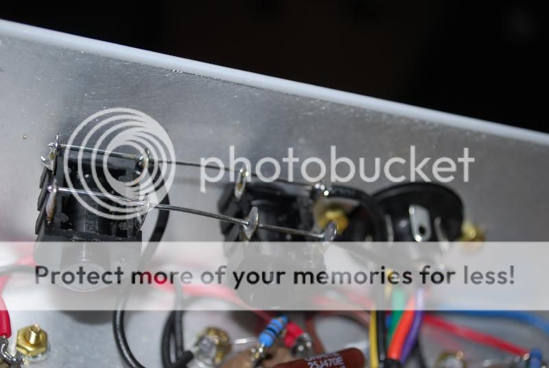
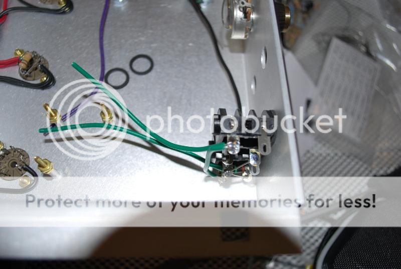
#13 Wired up the input jacks as well, the directions didn't really make sense at first when it tells you to cut a 8" length of black wire and strip 2", but the point of the black wire is it gets grounded to the buss wire across the pots. I actually missed this step till I went down some more and saw them ground it. A tip to wiring the input jacks is you can mount them from the outside and do it there and then move them inside afterwards.

DSC_0038.jpg


DSC_0039.jpg


DSC_0041.jpg


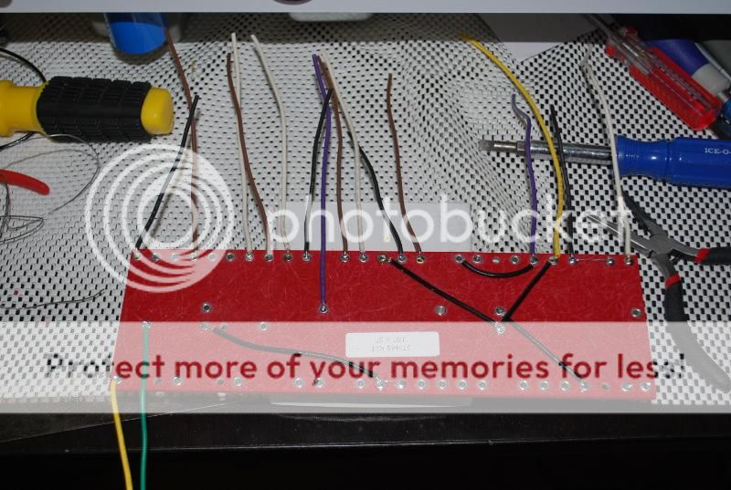
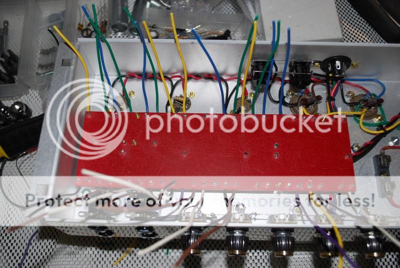
#14 Here's the PTP board prepped and being installed in the chassis. For wiring the PTP board you can either wire the wire through and twist it on the other end, or just put in part of it and solder from there, the risk of doing this is if you heat up the top too much when soldering components you have the risk of the wiring on the other end falling out.

Since the turrets are hollow, one tip to solder it to look good is to add an additional amount of solder to the tip of your iron, then touch it against the rings, this should go make the solder go over the ring and not into it. Quick in and out process for a clean look.

DSC_0042.jpg


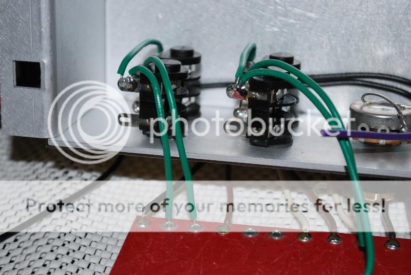
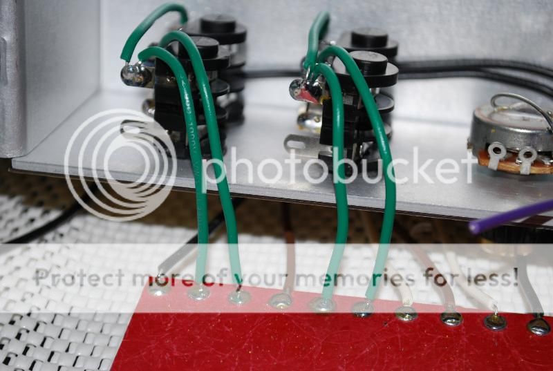
#15 Soldering the input jacks to the board. Here just follow instructions (tilt chassis on its side) and you should be fine. I forgot the picture for the purple/yellow wire from the impedance switch/output socket but just follow directions and you will be fine.

DSC_0049.jpg


DSC_0050.jpg


#16 Board mounted into the chassis.

DSC_0052.jpg


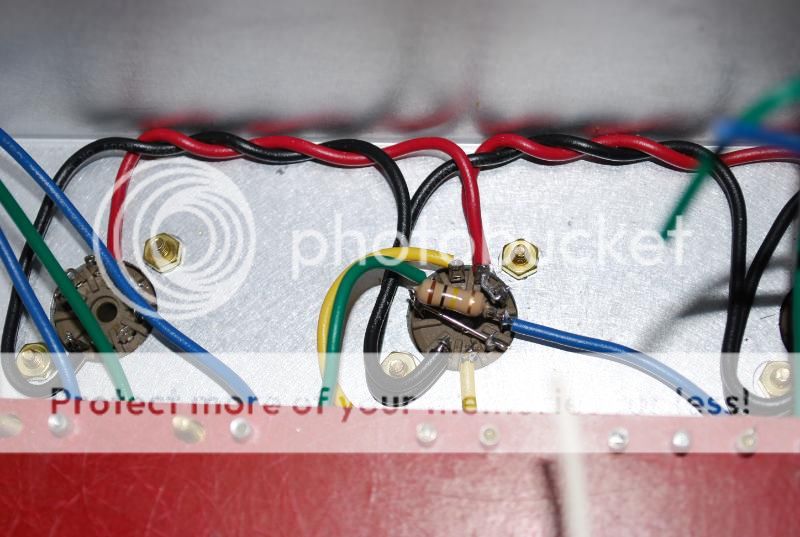
#17 Wired up V2, pretty straightforward, double check your lengths then cut/solder.

DSC_0054.jpg
 
You gotta be getting excited about fireing this baby up by now? Are you gonna put a MV on it?
 
looks good will, i would love too hear that bad boy when it's done.
 
Good luck Will! I can't wait to see/hear the final product.
 
Lp Freak":3mm3di9e said:
You gotta be getting excited about fireing this baby up by now? Are you gonna put a MV on it?

Very! Seems like I'm pretty close to finishing up the build, probably hoping to finish this weekend if I don't screw anything up, as for MV.. going to put the Lar-Mar PPIMV in it, I left out the one step to solder the green/orange wires to the board because of it. Still deciding on placement of the PPIMV, it's either replace the 2nd speaker jack with it or drill a new hole next to it. I'm also planning on putting a Zero Loss FX loop in it to, need to print out the template for drilling the holes correctly. :thumbsup:
 
goldwing68nv":3gd89uxt said:
GREAT kits,AWESOME amps :)

Definitely! It's amazing how idiot-proof his instructions are. Can't really go wrong with doing a Metro kit as your first build to learn a thing or two.

bravedude2":3gd89uxt said:
looks good will, i would love too hear that bad boy when it's done.

Thanks Henry! For sure.

gibson5413":3gd89uxt said:
Good luck Will! I can't wait to see/hear the final product.

I hope all goes well when firing this up for the first time :scared:
 
cyndicate":qfewp23g said:
Lp Freak":qfewp23g said:
You gotta be getting excited about fireing this baby up by now? Are you gonna put a MV on it?

Very! Seems like I'm pretty close to finishing up the build, probably hoping to finish this weekend if I don't screw anything up, as for MV.. going to put the Lar-Mar PPIMV in it, I left out the one step to solder the green/orange wires to the board because of it. Still deciding on placement of the PPIMV, it's either replace the 2nd speaker jack with it or drill a new hole next to it. I'm also planning on putting a Zero Loss FX loop in it to, need to print out the template for drilling the holes correctly. :thumbsup:
I'd fire up the amp without the MV at first just to make sure everything is right. Once you find that there's no problems, then add the it. The second speaker jack it a good location. Most people don't use the second speaker jack anyways. You can also return it back to stock if you ever decided to also going that route.

As far as the loop template, my printer didn't print out the correct size. It was close but wouldn't have worked so be sure to double check before drilling. :thumbsup:
 
Lp Freak":kvowst6e said:
cyndicate":kvowst6e said:
Lp Freak":kvowst6e said:
You gotta be getting excited about fireing this baby up by now? Are you gonna put a MV on it?

Very! Seems like I'm pretty close to finishing up the build, probably hoping to finish this weekend if I don't screw anything up, as for MV.. going to put the Lar-Mar PPIMV in it, I left out the one step to solder the green/orange wires to the board because of it. Still deciding on placement of the PPIMV, it's either replace the 2nd speaker jack with it or drill a new hole next to it. I'm also planning on putting a Zero Loss FX loop in it to, need to print out the template for drilling the holes correctly. :thumbsup:
I'd fire up the amp without the MV at first just to make sure everything is right. Once you find that there's no problems, then add the it. The second speaker jack it a good location. Most people don't use the second speaker jack anyways. You can also return it back to stock if you ever decided to also going that route.

As far as the loop template, my printer didn't print out the correct size. It was close but wouldn't have worked so be sure to double check before drilling. :thumbsup:

I guess I should go back and add the green/orange wires :lol: :LOL: Thanks! I have the FX loop drilled into my 100w chassis already so I think I'll just use that as my template.
 
I think they give the dimensions on the template also. Check it out.
 
Lp Freak":32hrzslc said:
Is it done????

Almost :) I'm missing a 68K resistor that goes on the bias control, for some reason can't find it, should arrive on Wednesday then I can start testing it.
 
cyndicate":3ap6kjf1 said:
Lp Freak":3ap6kjf1 said:
Is it done????

Almost :) I'm missing a 68K resistor that goes on the bias control, for some reason can't find it, should arrive on Wednesday then I can start testing it.

So how many hours did it take?
 
dstroud":2xu3w8rb said:
cyndicate":2xu3w8rb said:
Lp Freak":2xu3w8rb said:
Is it done????

Almost :) I'm missing a 68K resistor that goes on the bias control, for some reason can't find it, should arrive on Wednesday then I can start testing it.

So how many hours did it take?

Haven't really been keeping track of time, but I think around ~16 hours total so far.
 
Back
Top